After completing a set of courses like those, you will arrive at your work the next day and then you may feel frustrated when noticing that the actual concern is not finding the answers, but making them likable even if they are not accurate and impartial.
In my opinion, before facing a Data Science / BI project you should ask yourself (or your board of directors):
Do you know the questions?
Do you have good data to work with?
Will you assume the answers though you don’t like them? (my fav)
There are several ways to authenticate our calls to the server. Here we will use a server certificate instead of Windows or HTTP Header Authentication.
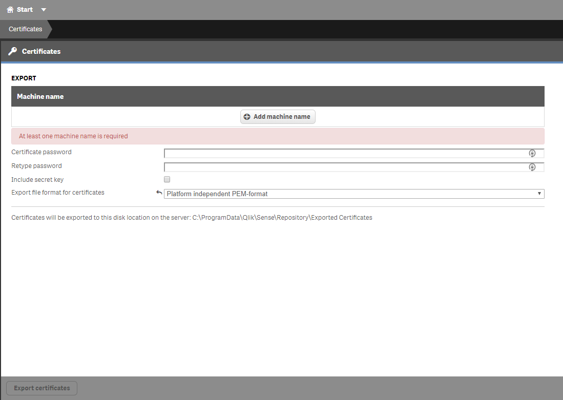
To export the server certificates, we need to access the QMC console with admin privileges. Once you are logged into the QMC, click in the last option on the left menu “Certificates”.
You will need to enter a machine name and also a password if you want to protect your certificate. Remember, if you don’t specify a password, anyone who has access to the certificate file will have the capabilities of an admin via the Qlik Sense API.
Change the file format of the certificate to .pem and note the location where the .zip file that contains the certificates will be saved.
If you go now to the folder mentioned above and everything went ok, you will find a zip file. Unzip the file and copy both files inside (client.pem & client_key.pem) into a safe folder or an usb pen that we will reference later.
Now, let’s go to our Linux station to create the utility script that we can use to start Qlik Sense tasks.
Of course, the Qlik Sense server has to be accessible from this station.
1.- Create a folder to store both the script and the certificate files
mkdir /opt/qliktasks
2.- Access the new folder and create a new one to store the certificate files
cd /opt/qliktasks

mkdir cert
3.- Copy the cert files from your usb device or the folder where you stored them before. Once you’ve finished, there should be two files inside the cert folder you created in step 2.
/opt/qliqtasks/cert/client.pem

/opt/qliqtasks/cert/client_key.pem
4.- Now, let’s create the sh script:
4.1.- Inside /op/qliktasks folder open nano or vim to create the file taskStart.sh
nano taskStart.sh
4.2.- Make up a 16 characters long key that you will specify later in the query string and a header of the curl request. For instance:
MySixteenLongKey

1234567890123456
4.3- Copy the following content inside the file updating the files path and the 16 long key. This is a very important step because the files need to be specified with an absolute path.
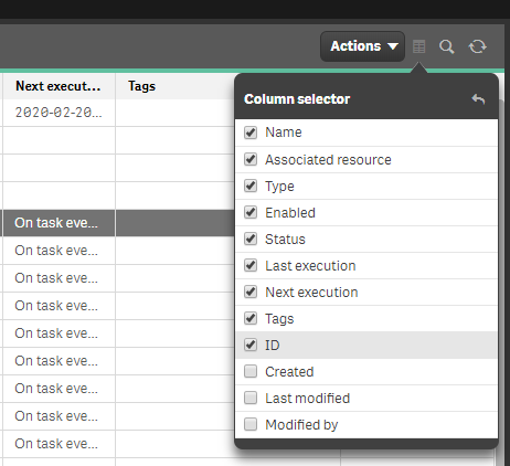
Go to QMC tasks panel and find the column menu in the top right corner. Simply activate the ID checkbox and copy from the new column the UUID of the task you need to invoke.
Redmine is probably the best open source ticketing application. We have been using it for some years and had no problem at all.
Though you can define your own workflows and status transitions I miss a feature: automatically closing issues that have been solved during a certain number of days.
There exists a plugin to do so, but if you don’t want to deploy third-party plugins or you just want to customize the way you close the issues, here you have a couple of MySQL Scripts to automate this task (you can program a cron entry for that).
The first script retrieves all the issues ids that have been in solved status during more than the specified number of days
CREATE DEFINER=`root`@`%` PROCEDURE `sp_close_resolved_redmine`(
IN `in_days` INT
)
LANGUAGE SQL
NOT DETERMINISTIC
CONTAINS SQL
SQL SECURITY DEFINER
COMMENT ''
BEGIN
    declare v_id integer;
    declare v_finished bool;
    declare res_issues cursor for
    SELECT id
    FROM redmine.issues
    WHERE status_id = 3
    AND TIMESTAMPDIFF(DAY, updated_on, CURRENT_TIMESTAMP) > in_days;
    declare continue handler for not found set v_finished = true;

    open res_issues;
    res_issues: loop
        fetch res_issues into v_id;
        if v_finished = true then
            leave res_issues;
        end if;
        call sp_cierra_issue_redmine(v_id);
    end loop res_issues;
    close res_issues;
END
The second script is invoked by the one above passing the issue id to be closed
CREATE DEFINER=`root`@`%` PROCEDURE `sp_cierra_issue_redmine`(
                IN `in_id` INT
)
LANGUAGE SQL
NOT DETERMINISTIC
CONTAINS SQL
SQL SECURITY DEFINER
COMMENT ''
BEGIN
    declare v_id            integer;
    declare v_author_id     integer;
    declare v_assigned_to   integer;
    declare v_status        integer;
    declare v_id_journal    integer;

    select author_id, assigned_to_id, status_id into v_author_id, v_assigned_to, v_status
      from redmine.issues
     where id = in_id;

    #Update issue status and assign to author
    update redmine.issues
       set assigned_to_id = v_author_id,
           status_id = 5,
           updated_on = current_timestamp,
           closed_on = current_timestamp
     where id = in_id;

    #Create a new journal for the issue
    insert into redmine.journals (journalized_id, journalized_type, user_id, notes, created_on)
                          values (in_id, 'Issue', 1, 'Automatically closed after 7 days solved', current_timestamp);

    #Get the journal id we have just inserted
    select max(id) into v_id_journal
      from redmine.journals
     where id = in_id;

    #Create two new entries in journal details, one for assigned_id and another one for status_id
    insert into redmine.journal_details (journal_id, property, prop_key, old_value, `value`)
                                 values (v_id_journal, 'attr', 'assigned_to_id', v_assigned_to, v_author_id);

    insert into redmine.journal_details (journal_id, property, prop_key, old_value, `value`)
                                 values (v_id_journal, 'attr', 'status_id', v_status, 5);
END
Since I bought my Ender 3 I have been looking for a hairspray with the minimum odor. I hate the cheap perfume smell floating around in the room where I make things.
I first try the most famous 3D printing hairspray in Spain: Nelly. It doesn’t smell too much, but it does.
A second try was for Mercadona’s “Fuerte” one. It smells better and adhesion is quite good.
I felt very good with this last one, but after some more printings… the room smells like a granny hairstyle contest.
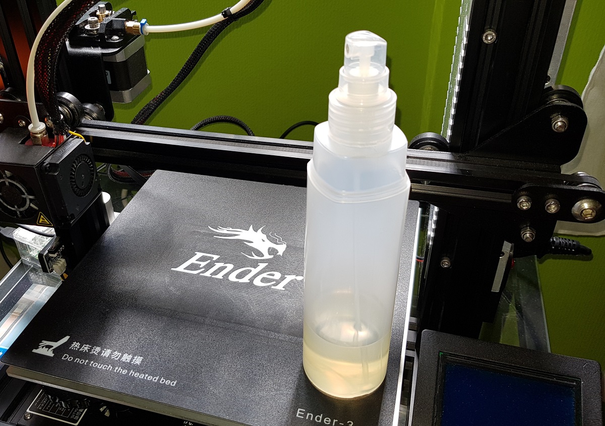
After thinking a lot on it I found a solution. Some years ago I played with pine resin to make a homemade soldering paste. Though the results where satisfying, I stopped using that substance because once diluted in alcohol, when the dissolvent evaporates it remains a surface extremely sticky. That is exactly what I want now for my printing bed: a sticky surface.
Pine resineFinished adherence improver
Today I’ve tried the first formulation with very good results:
Ingredients:
50 grams of Ethylic Alcohol
3 grams of pine resin
The recipe is quite simple. All you have to do is follow the next steps:
Make powder a couple of resin stones (1cm side each one).
Pour the powder and the alcohol in a small bottle, close it and stir until the resin dissolves completely.
It’s done.
Put the resulting liquid into a spray bottle and you have a ready to use adherence improver that doesn’t smell at all.
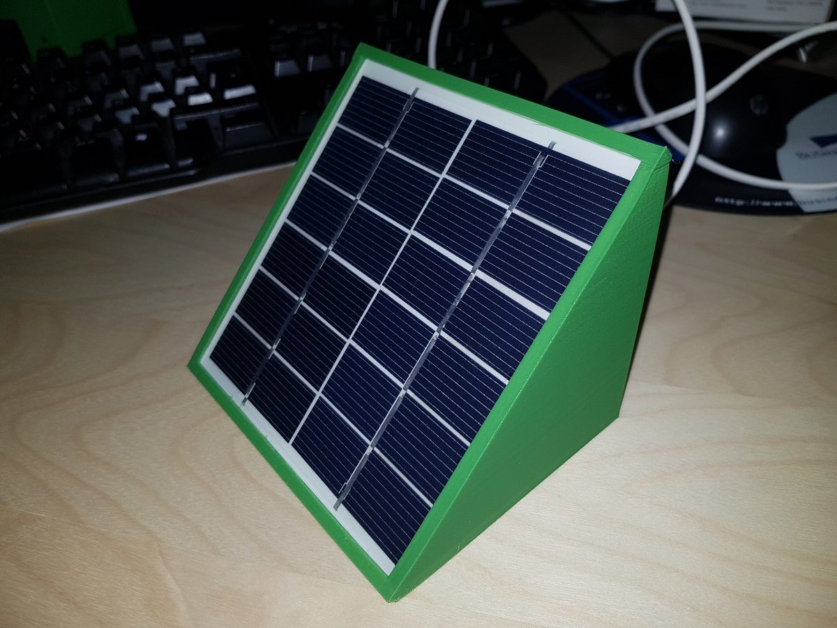
Some 3D print jobs may take hours to finish. When printing to an Ender 3 (and I guess there are other printer models with the same issue) even if the job has finished, the printer stays on and the power module fans continue running. If this happens during night hours, it means a noise that we can avoid easily.
We have a lot of possibilities to achieve our goal, but I don’t want to plug any wire to the Raspi GPIO to control a relay board. I instead used a Sonoff Switch to control a standard multiplug.
We will cover only the switching solution assuming that you have already your Octoprint system connected to your printer and working.
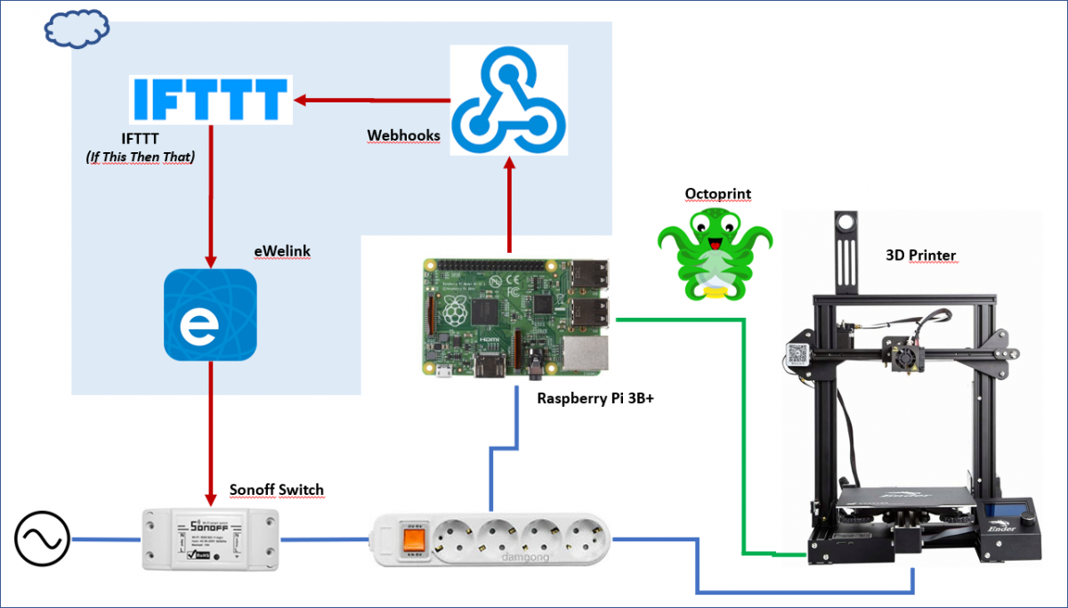
The solution will perform the next steps to switch off the printer and the Raspi:
The printing job will run as usual.
When the job is completed, Octoprint will check for any event listener already configured (in config.yaml file)
Our event configuration will trigger a system command consisting of a Wget to contact to Webhools
Webhooks will notify IFTTT about the finished printing job
IFTTT will take into account (with a programmed filter) the time when the event occurs to switch off (or not) the Sonoff Switch
IFTTT will send a message to eWelink platform to switch off the device
eWelink platform will tell our device to switch off
Though it seems there is a lot of work to do, you’ll see it’s quite easy to set up everything and most of the steps are performed in the background by IFTTT platform.
List of components
IFTTT account: you can use your Google account to log in
This step is quite easy. All you have to do is cutting the multiplug wire to insert the Sonoff switch in it. Be aware that Sonoff switch has an input and an output.
There are a bunch of videos and tutorials about how to do this.
2.- Set up your Sonoff Switch
Use the app installed on your Android phone to set up the switch. Just to clarify how the Sonoff switch works take into account these next points:
The switch connects to your Wifi router:
All the communication occurs between the switch and eWelink server. You cannot (unless you reprogram the switch board) communicate directly to it through your LAN.
To set up the switch using its App, you have to be connected to the same Wifi network at the moment of setup. This point is very important because you may have two wifi networks at home (one for 2.4GHz devices and another one for 5GHz) and probably you connect your mobile to 5GHz one. If you don’t connect to 2.4GHz at the moment you configure your switch you will be telling your device to connect the network you are in and it will not be able to connect to that 5GHz wifi. It is only capable to connect to 2.4GHz AP, so please before configuring the device connect your mobile to your 2.4GHz wifi AP. This is only for during setup process. Once the device is configured you can return your mobile to your 5GHz wifi.
Once the Sonoff device is configured, you have several alternatives to switch it on/off:
Using eWelink App
Using Google Assistant
Using IFTTT (If This Then That) platform. And this will be our choice for this solution.
Just in case you have any issue while reproducing the activation steps shown in the video, here you have the official link to the eWelink setup process.
At this point, you should be able to switch on/off your device by using eWelink App on your Android phone. If you are not, please do not continue beyond this point and review all the configurations.
3.- IFTTT Applet Set up
Now you have your device reachable in the cloud it’s the moment to create an applet in IFTTT. You will use a free account and some of the characteristics of your applet are premium, so you will be limited and you will not be able to publish your applet for others and it will just be available for you. That’s no problem at all.
Log into IFTTT with your account (or even better use your Google one) and then follow the steps shown in the next video:
The applet is now available and you can invoke it in two different ways:
A GET request: from any browser, CURL, WGET, etc
A POST request: and optionally specifying a JSON body with additional data (a security token for instance)
We will use the first option now.
The first thing is to find the key to invoke Webhooks. That key is generated automatically by the platform and it can be easily changed on demand.
To find it, follow the steps shown in the video, then copy it down:
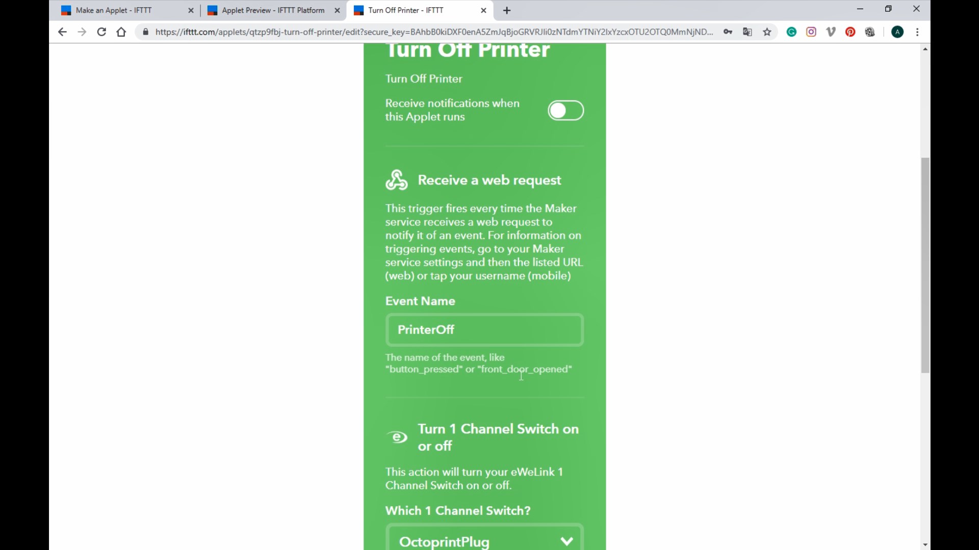
So, at this point, we have everything to invoke our applet:
Event Name: PrinterOff
Webhooks Key: your_webhooks_account_key
Remember the Event Name is not the Applet Name, but the name you specified when you activated the applet:
Replace the key with the value assigned to your account, copy the full URL and paste it on any browser.
If everything goes right you will receive a reply like this
Congratulations! You've fired the PrinterOff event
Change the key value and the response will be an error, but take care because if you change the event name, though it doesn’t exist, it will reply with a success message. So, if you see everything seems to work but the applet seems to be not invoked review the event name in the URL.
4.- Add two applets to control the printer manually (OPTIONAL)
We have an applet that we will use to switch off our printer from Octoprint when a print job is done, but we need to use the eWelink application to switch on/off the printer.
To make things easier, we can add two more applets. Do not modify the one we’ve just created as we will use it after.
Following the shown steps in two videos above, create and activate these two applets:
Applet 1:
On New applet screen
Trigger: Webhooks
Applet Name: ManPrinterOn
Applet Description: Manually switch on the 3D printer
Action: eWeLink
On Enabling Screen
Event Name: ManPrinterOn
Which channel: yourDeviceName
On/Off: ON
Applet 2:
On New applet screen
Trigger: Webhooks
Applet Name: ManPrinterOff
Applet Description: Manually switch off the 3D printer
Action: eWeLink
On Enabling Screen
Event Name: ManPrinterOff
Which channel: yourDeviceName
On/Off: OFF
With our two new applets, we can switch on/off our printer from any browser. To make this task easier, we will create two batch files (if you are a Linux user it will be easy to transform the Windows .bat files)
Install Wget for Windows. The easiest way is to download the installer from SourceForge: Wget for Windows
Create a folder inside your user folder named scripts.
Create two .bat files inside the scripts folder and adapt the content of the files to your Ids, Keys, etc.
echo off
wget https://maker.ifttt.com/trigger/YOUR_EVENT_NAME/with/key/YOUR_WEBHOOKS_KEY -O /dev/null
Both files are the same thing when invoking IFTTT platform and just change the event name (to switch on or off), but the first file, additionally will wait for 45 seconds and open a Chrome instance with the Octoprint URL. Change this to adapt to your configuration or simply remove these lines if you don’t want Octoprint to be invoked automatically when switching on your printer.
Add to direct links to these files to your desktop and all you have to do to switch on or off your printer is double-click on them.
5.- Make applet conditioned to time
Probably you will want your system not turning off each time a print job is finished. Imagine you want to send two or more short jobs to your printer manually.
To prevent this from happening we are going to make our Applet conditioned to time using the Filtering capabilities of IFTTT. This is the premium feature I told you before, but you can use it for your own Applets (you cannot publish them to be used by others).
Coding a filter for an IFTTT Applet is quite easy. It uses Javascript and standard libraries.
To implement our filter all you have to do is deciding what time do you consider the limit when the printer should be turned off automatically. In my case, I chose between 23:00h and 08:00h, because I never print something beyond that time and wait for it to finish.
Here you have a video showing the necessary steps and how to reach the Logging Screen to check if your applet is running ok. Take note that the video doesn’t show exactly the same code as the one mentioned above.
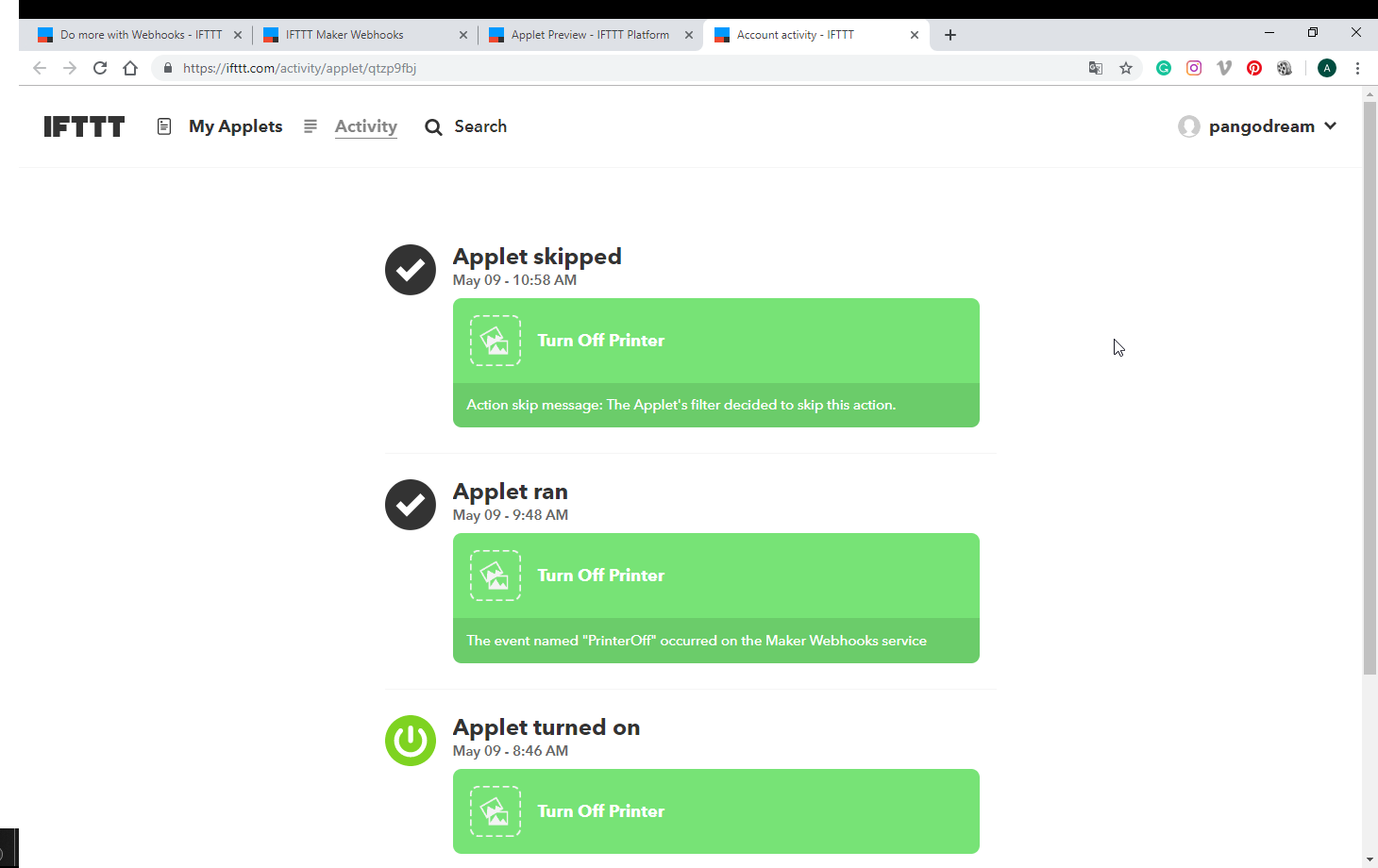
Now, if you invoke your applet from a browser and the limit time you configured in the code has not been reached, the applet execution should be skipped. You can check it in the logging screen and may show something like this:
IFTTT Applet event skipped
6.- Configure event in Octoprint
We need to tell Octoprint what to do when a PrintDone event occurs.
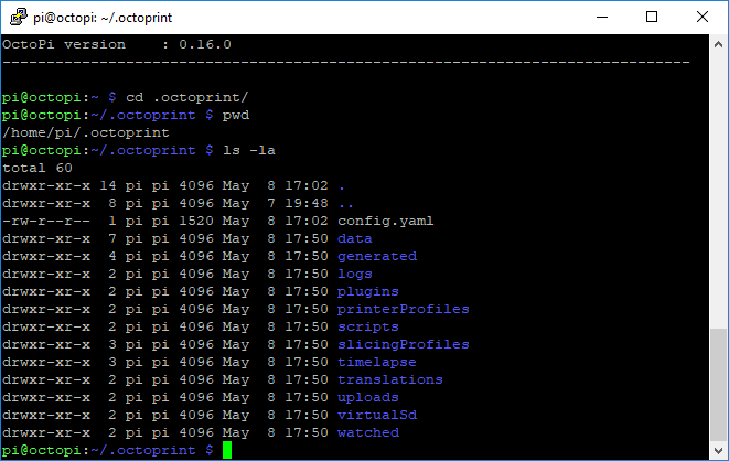
Locate the config.yaml file on your Octoprint installation. If you are using a Raspberry Pi it will probably be here:
Octoprint config.yaml file
Edit the configuration file using your favorite editor and add the following lines to the end of the file.
Replace YOUR_EVENT_NAME and YOUR_WEBHOOKS_KEY with the correct values you obtained in previous steps.
Now, when Octoprint finishes a job, it will invoke your IFTTT Applet and if it occurs after the time you configured in the Applet filtering it will switch off your printer and Raspi.
Two days ago I deployed an Octoprint system for my Ender 3. Octoprint is the leading application for remote controlling 3D printers. It needs to be deployed on a host connected to the 3D printer and takes control of everything, allowing you to interact with your printer remotely (web or app).
I have in mind a very less ambitious project consisting of an ESP32 combined to a USB host shield that will allow checking the printer status for less than 10€, but I am still waiting for some parts to arrive from China and of course, it has nothing to do with Octoprint.
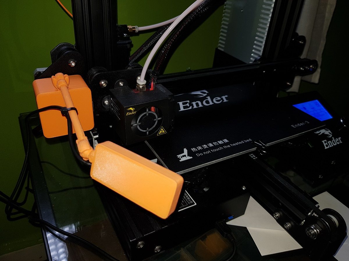
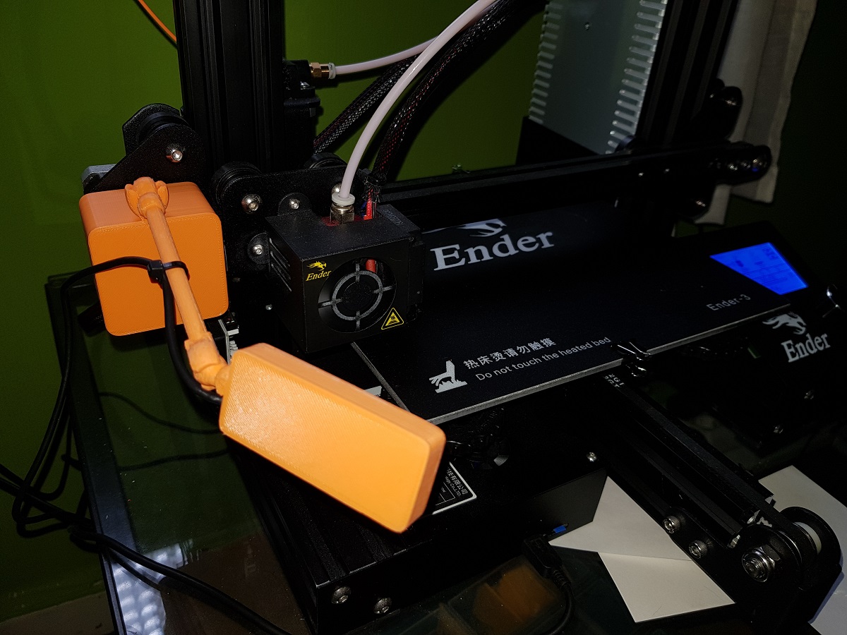
One of the most attractive features of Octoprint is the possibility to connect a webcam to the system so that you can see what’s really happening to your printed piece.
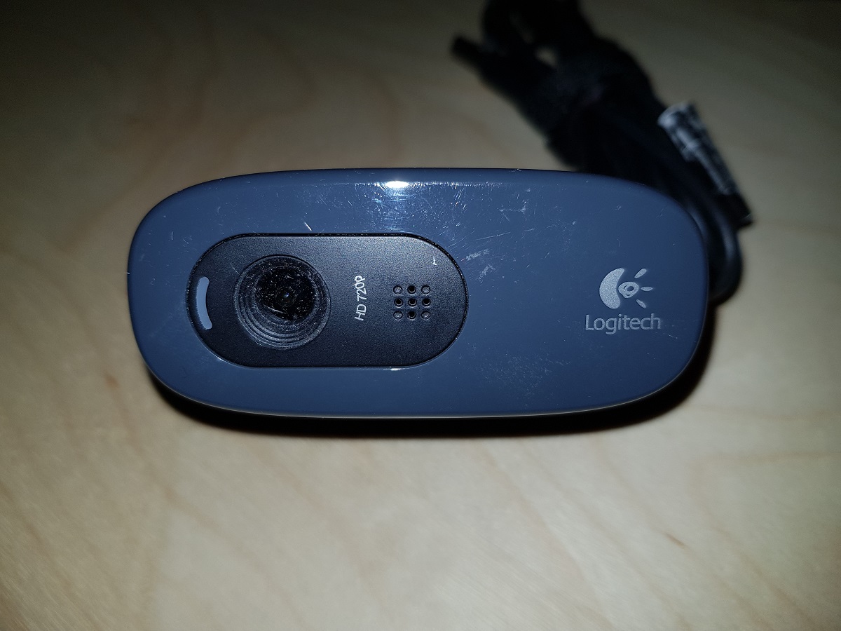
I had a Logitech C270 forgotten in a drawer, so I decided to use it for my printer. I tried to hang it from the upper crossbar, but the printing vibrations made it quite unstable. I also used a tripod, but it makes no sense to set up a tripod each time you print something.
Logitech C270 Webcam
Transforming a Logitech Webcam into an Ender 3 Webcam
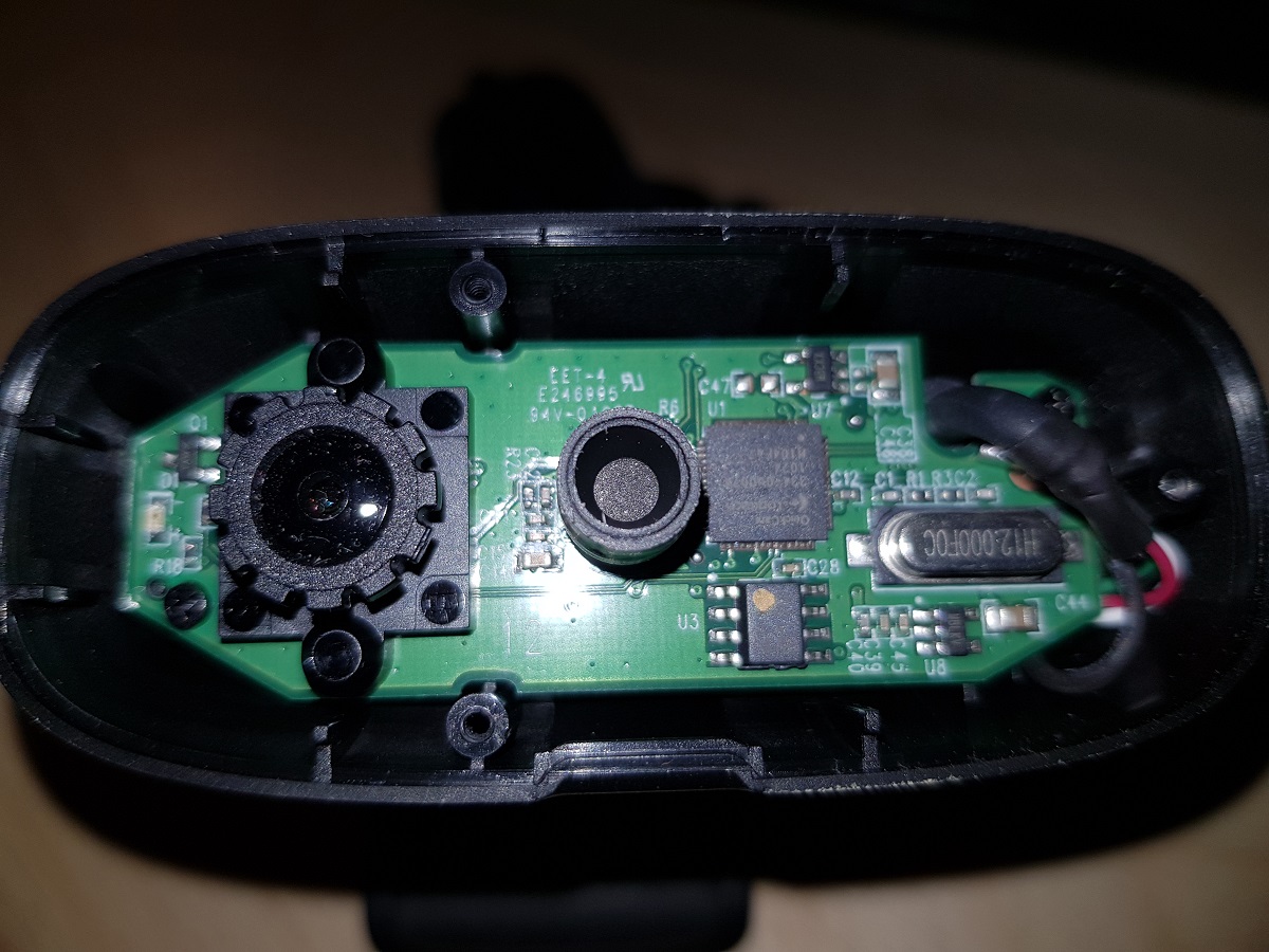
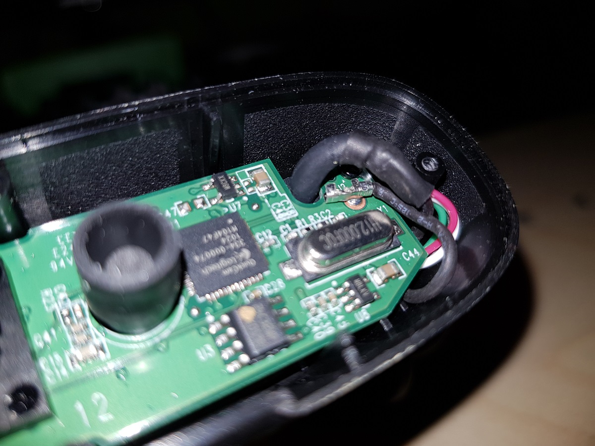
I opened the webcam to measure the internal pieces in order to design a new case for them. The cam consisted only of a tiny board with a focusable camera lens attached to it. This was a good surprise for me because, though the Logitech C270 is a quite good camera, the focus distance is fixed a bit further than the required for the printer and if I can adjust the focus distance it will be much better.
Inside Logitech C270 (note the adjustable lenses)
To avoid breaking the original case, I had to desolder a wire.
Logitech C270 Wire to be desoldered
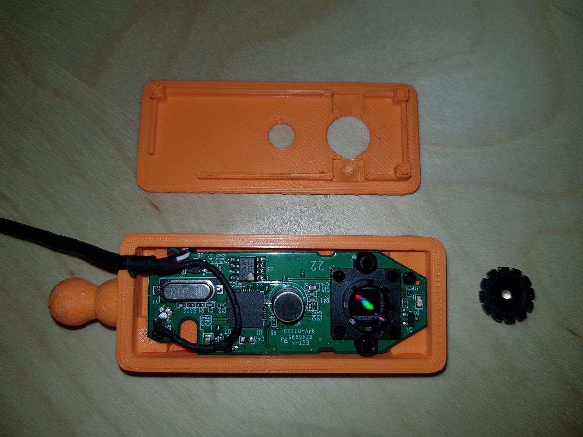
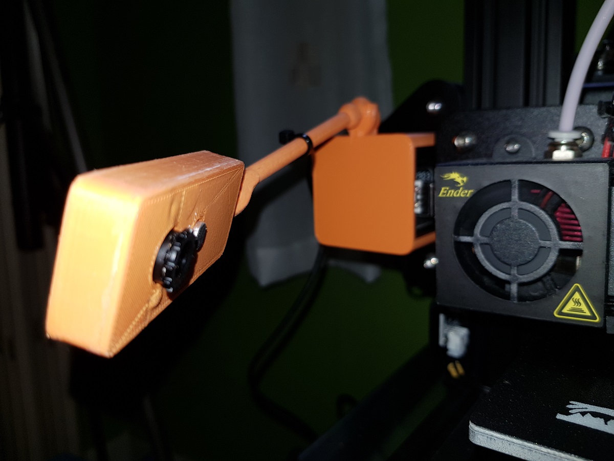
After measuring the board, I designed a box as thin as possible and mounted the board inside it.
Inside Ender 3 Webcam
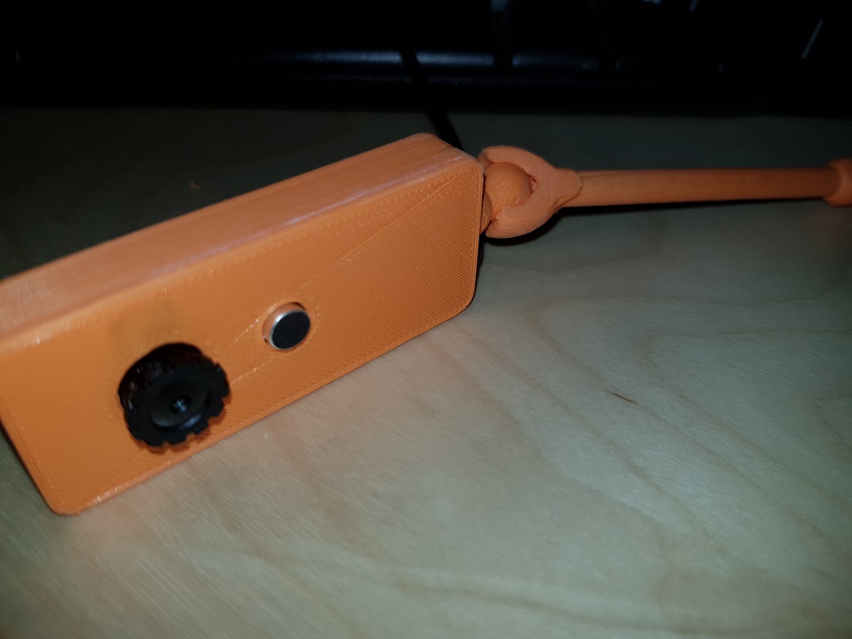
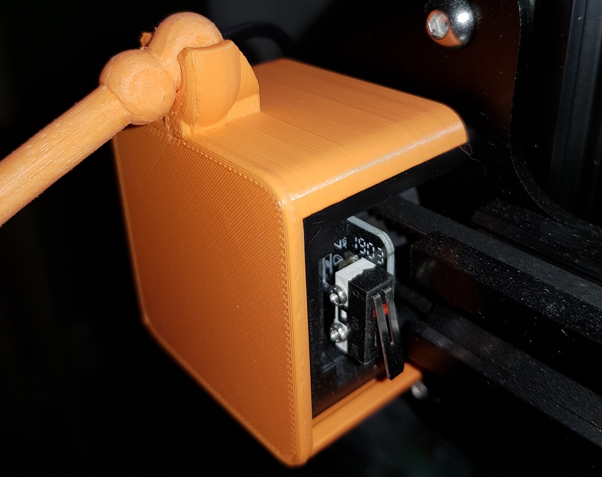
The complete system consists of a box for the cam, a bone, and a base:
Assembling webcam to the boneBoneEnder 3 Webcam baseEnder 3 WebcamEnder 3 Webcam
Buying a second-hand Kinect is a cheap option to get a 3D scanning capable device. Though it is not designed specifically for that purpose it can, using the right application, create a 3D model of an object, a room or a person.
I’ve tried several times to install the XBOX 360 Kinect to my Windows PC with no success, but finally, I’ve made it work.
Xbox 360 Kinect
There is a Windows version of Kinect. It costs about 155€ and I guess it is easier to install on a PC, but I had no intention to expend that money while there are second-hand units for about 20€. A friend of mine bought one for 6€!
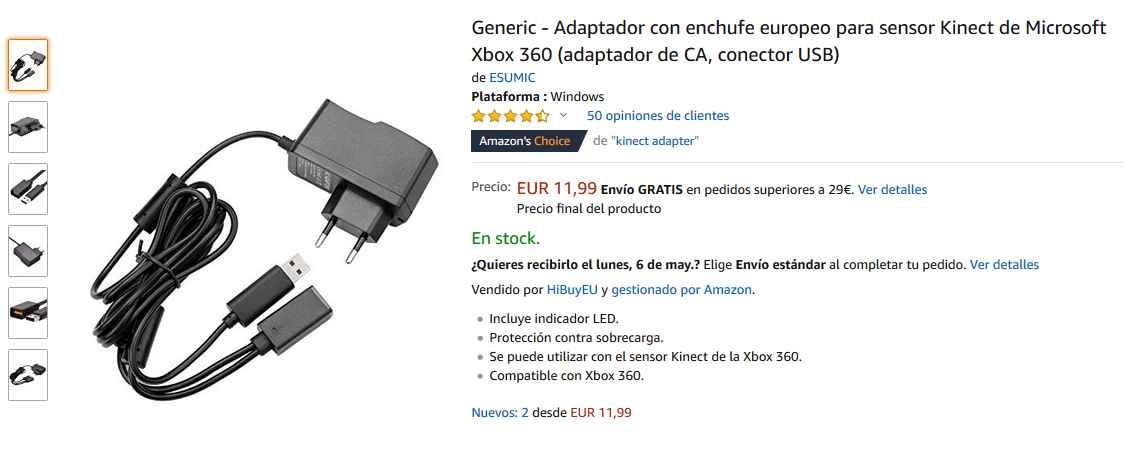
What do you need to connect the Xbox device to Windows? You need an adapter that you can order to Amazon and it costs only 12€.
Kinect adapter for PC
The converter just feeds with some extra current to our Xbox Kinect and also adapts the Xbox plug to a standard USB 3.0.
There are no more hardware requirements. All you need is to install the software to make it work, and at that point is where I got in troubles.
If you read the available tutorials on the web, the first step is installing Kinect for Windows SDK and after that connecting your Kinect to any USB 3.0 port. The device should be autodetected and de Kinect devices (camera, audio, and motor) will be shown on the Windows Device Manager.
Instead of that, what I got after installing was this:
Xbox NUI Motor
If this is also your case and you installed the latest version of Kinect for Windows SDK (version 2.0), try the following:
Unplug the Kinect from the USB 3.0 port
Remove the version 2.0 software (It is advisable though I didn’t remove it from my computer)
Install the previous version of Kinect for Windows SDK (version 1.8):
or you can download it from here if it is not available there.
Plug the Kinect again in
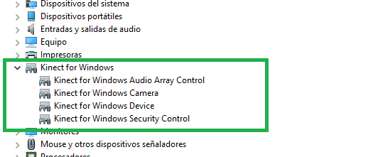
The correct drivers will be now installed
Kinect for Windows Devices
What todo do after that?
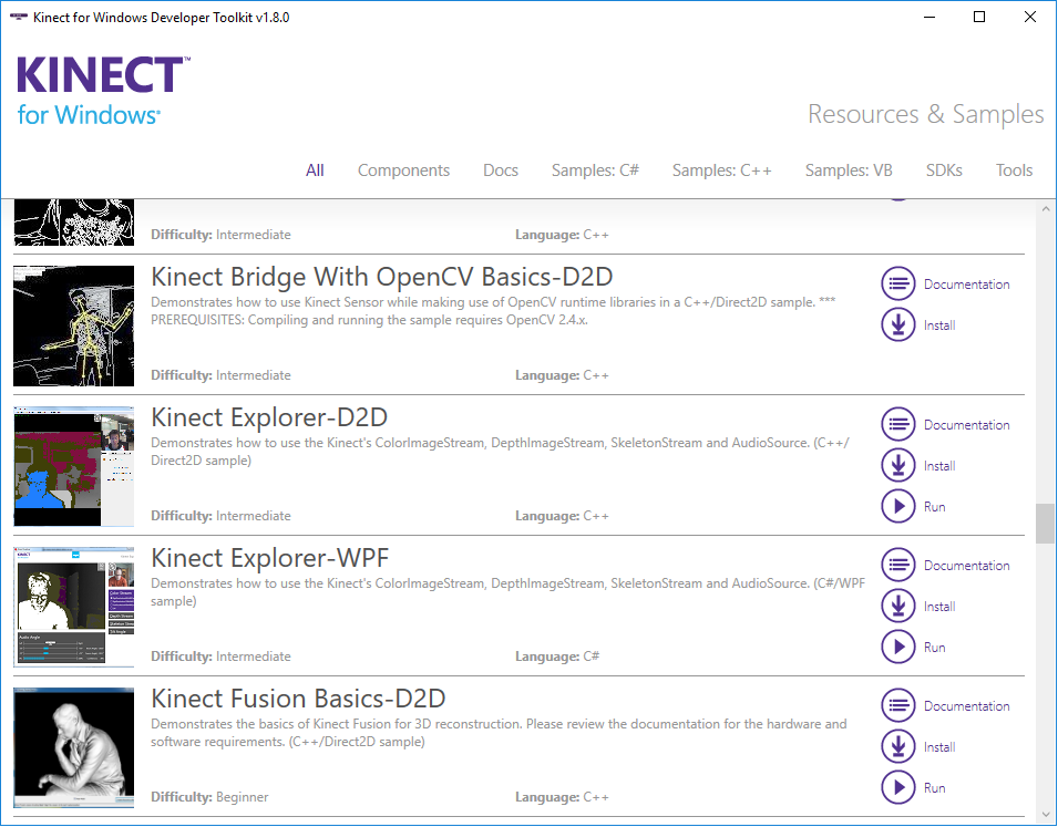
Try installing Kinect for Windows SDK Toolkit. It contains a lot of utilities and POCs to show the capabilities of Kinect technology for Windows.
Kinect for Windows Developer Toolkit
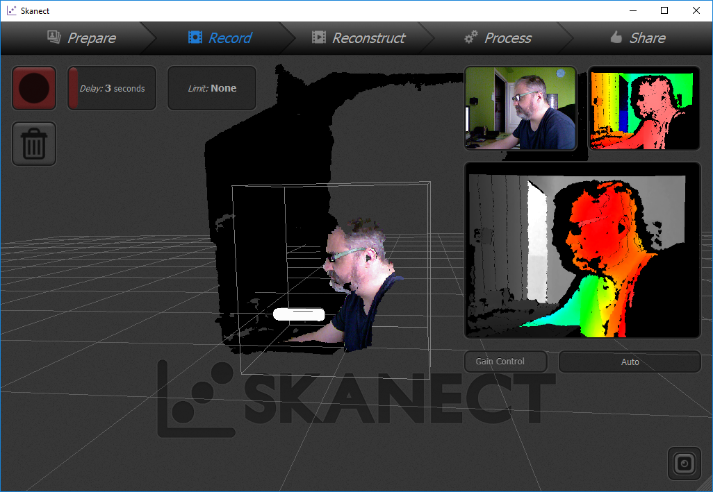
Scan an object or even yourself to make a 3D printing
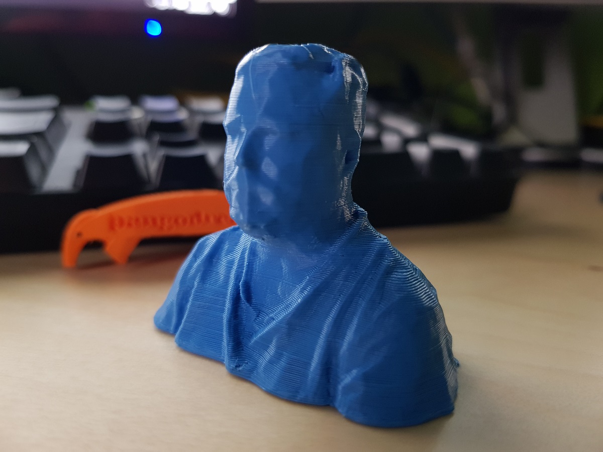
Skanect is a very good choice, but the free version only allows exporting a limited number of polygons. Nonetheless, the result is at least curious and you can recognize yourself though you print it using Blue Sky PLA)
Skanect Scanner
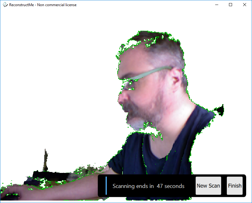
Reconstructme is also a good option, though is less straight and I think it is more focussed on making a virtual color model of the object.
Reconstructme while Scanning
Both Recostructme and Skannect will allow you to export a .obj or .stl file and then you can post-process it with the application of your election.
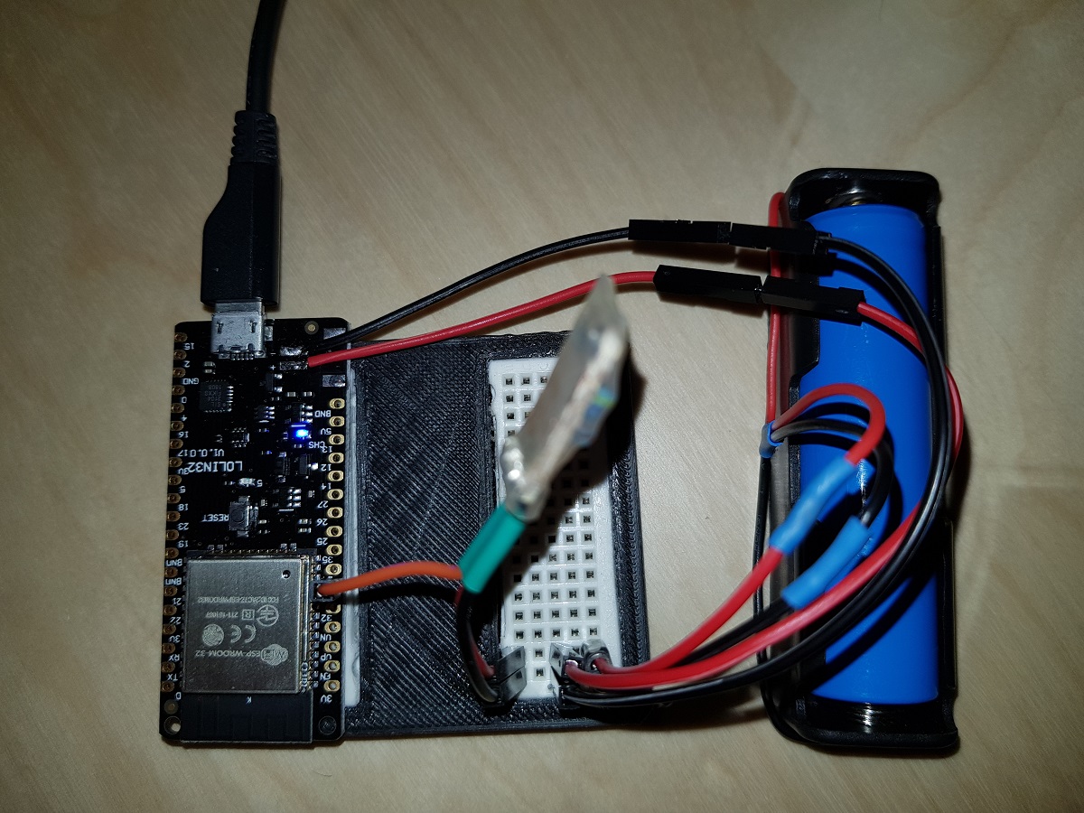
Some of the ESP32 development boards provide a 3.7 Ion-Li battery charger what is an advantage when we want to get a device with the minimum number of components.
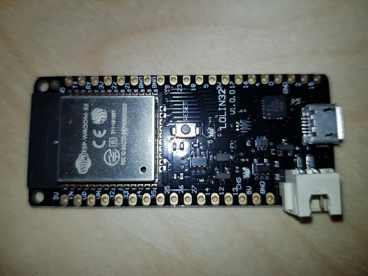
One of these boards is Wemos Lolin 32 (with battery charger) which costs about 7$ in eBay.
Wemos Lolin 32
When a battery is plugged in and the board is connected to a power source via the USB connector, the battery starts being charged.
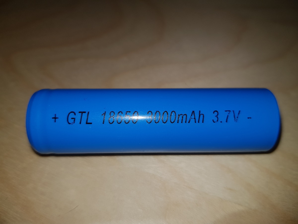
As the ESP32 board counts with several ADC pins, we can use one of them to check the voltage in between the two battery terminals. The only issue with this is that ADC pins expect voltages between 0 and 3.3 volts and our Ion-Li battery voltage range may reach 4.2 volts.
18650 Ion-Li Battery
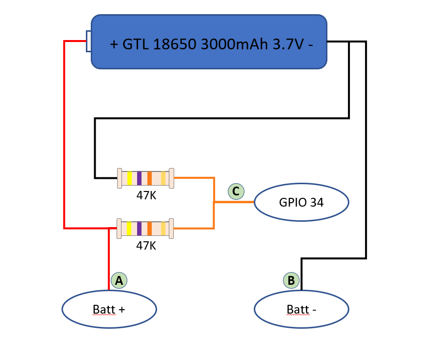
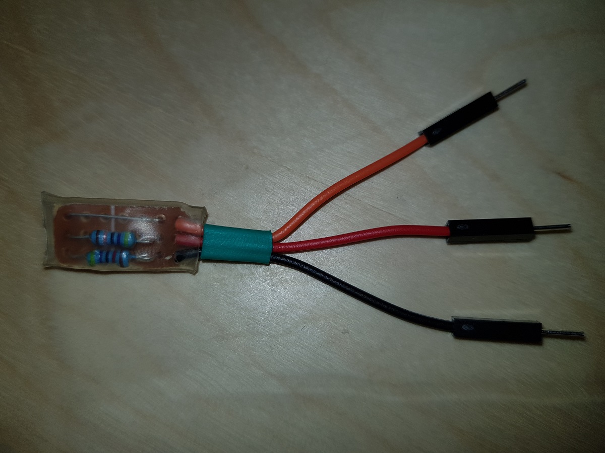
The solution to that is connecting a voltage divider to the battery, so we can divide the volts by 2 and the maximum value will be about 2.1 volts.
Voltage Divider SchemaVoltage Divider
Our voltage divider is built of two 47KΩ resistors. The total impedance between positive and negative terminals will be 94KΩ and that means a current of less than 5 50μA (microamperes, not milliamperes).(Thanks Jonathan)
Voltage Divider mounted on Lolin 32
With this, we can measure the voltage applied in GPIO34 (or any other ADC pins of our ESP32) and then, based on a conversion table, calculate the charge level of the battery.
First, we will get the value of ADC pin. This value may vary from 0 to 4096 depending on the voltage applied to it from 0V to 3.3V. So we can establish a constant to calculate the voltage applied to the pin based on its value. This constant, theoretically, will be 3300 / 4096 = 0.8056.
As we are applying a voltage divider and the voltage applied to the pin is half the voltage of the battery, our constant should be 0.8056 x 2 = 1.6113.
This means, for each unit in ADC pin we have 1.6113 mVolts applied to it.
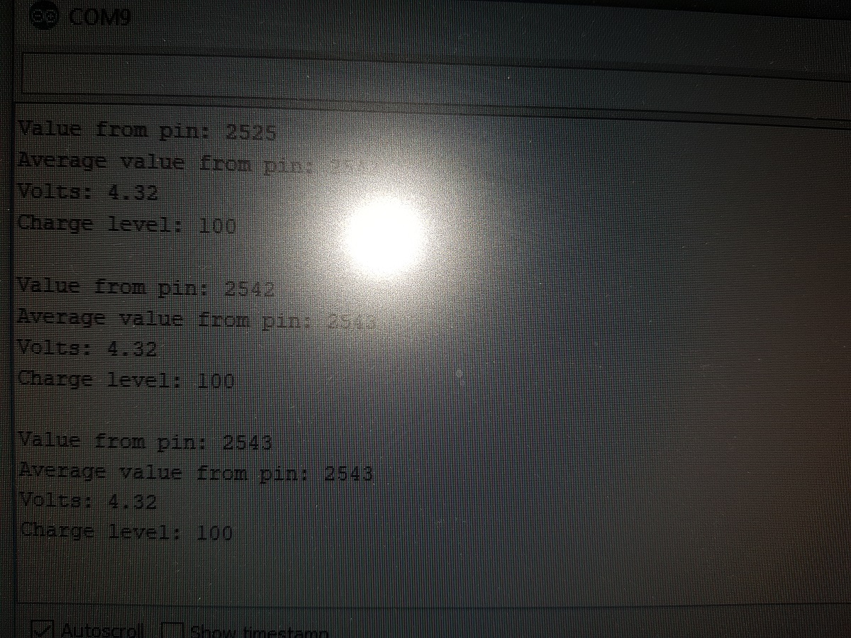
For instance, if we read the value of the ADC pin and get 2,543, then the voltage applied to the pin should be 2,453 x 1.6113 = 3,952V = 3.95V
ADC pins are not that precise, so the value of our constant should be adjusted to a level we consider it is valid for our components. In my case, after doing some testings I have concluded that the best value for the conversion factor is 1.7.
As I mentioned before, calculating the charge level is a direct translation from the voltage we obtained to a charge level by using a table.
All the code to make these calculations is contained in a library I have created for that purpose. You can find it in Github at Pangodream_18650CL.
All you have to do is downloading the .zip file and add it to Arduino IDE.
There is an example of using the library:
#include <Pangodream_18650_CL.h>

//#define ADC_PIN 34
//#define CONV_FACTOR 1.7
//#define READS 20

Pangodream_18650_CL BL;
/**
 * If you need to change default values you can use it as
 * Pangodream_18650_CL BL(ADC_PIN, CONV_FACTOR, READS);
 */

void setup() {
  Serial.begin(115200);
}

void loop() {
  Serial.print("Value from pin: ");
  Serial.println(analogRead(34));
  Serial.print("Average value from pin: ");
  Serial.println(BL.pinRead());
  Serial.print("Volts: ");
  Serial.println(BL.getBatteryVolts());
  Serial.print("Charge level: ");
  Serial.println(BL.getBatteryChargeLevel());
  Serial.println("");
  delay(1000);
}
And if everything works, it should display something like this on your serial terminal:
Reading battery charge level
This website uses cookies to improve your experience. We'll assume you're ok with this, but you can opt-out if you wish.AcceptReject
Privacy & Cookies Policy
Privacy Overview
This website uses cookies to improve your experience while you navigate through the website. Out of these, the cookies that are categorized as necessary are stored on your browser as they are essential for the working of basic functionalities of the website. We also use third-party cookies that help us analyze and understand how you use this website. These cookies will be stored in your browser only with your consent. You also have the option to opt-out of these cookies. But opting out of some of these cookies may affect your browsing experience.
Necessary cookies are absolutely essential for the website to function properly. This category only includes cookies that ensures basic functionalities and security features of the website. These cookies do not store any personal information.
Any cookies that may not be particularly necessary for the website to function and is used specifically to collect user personal data via analytics, ads, other embedded contents are termed as non-necessary cookies. It is mandatory to procure user consent prior to running these cookies on your website.