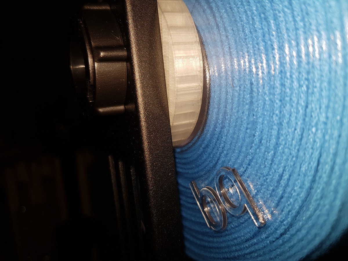
I’m quite happy with BQ Easy Go PLA filament. I have been using it during these last days and had no problem at all, but it is also true that I read some comments in Amazon before using it and there is an issue with this filament and Creality Ender 3 printers:
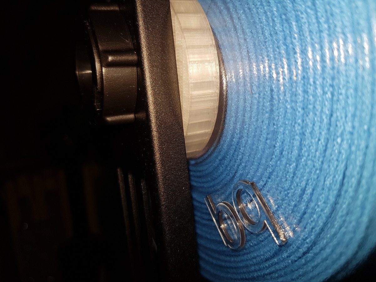
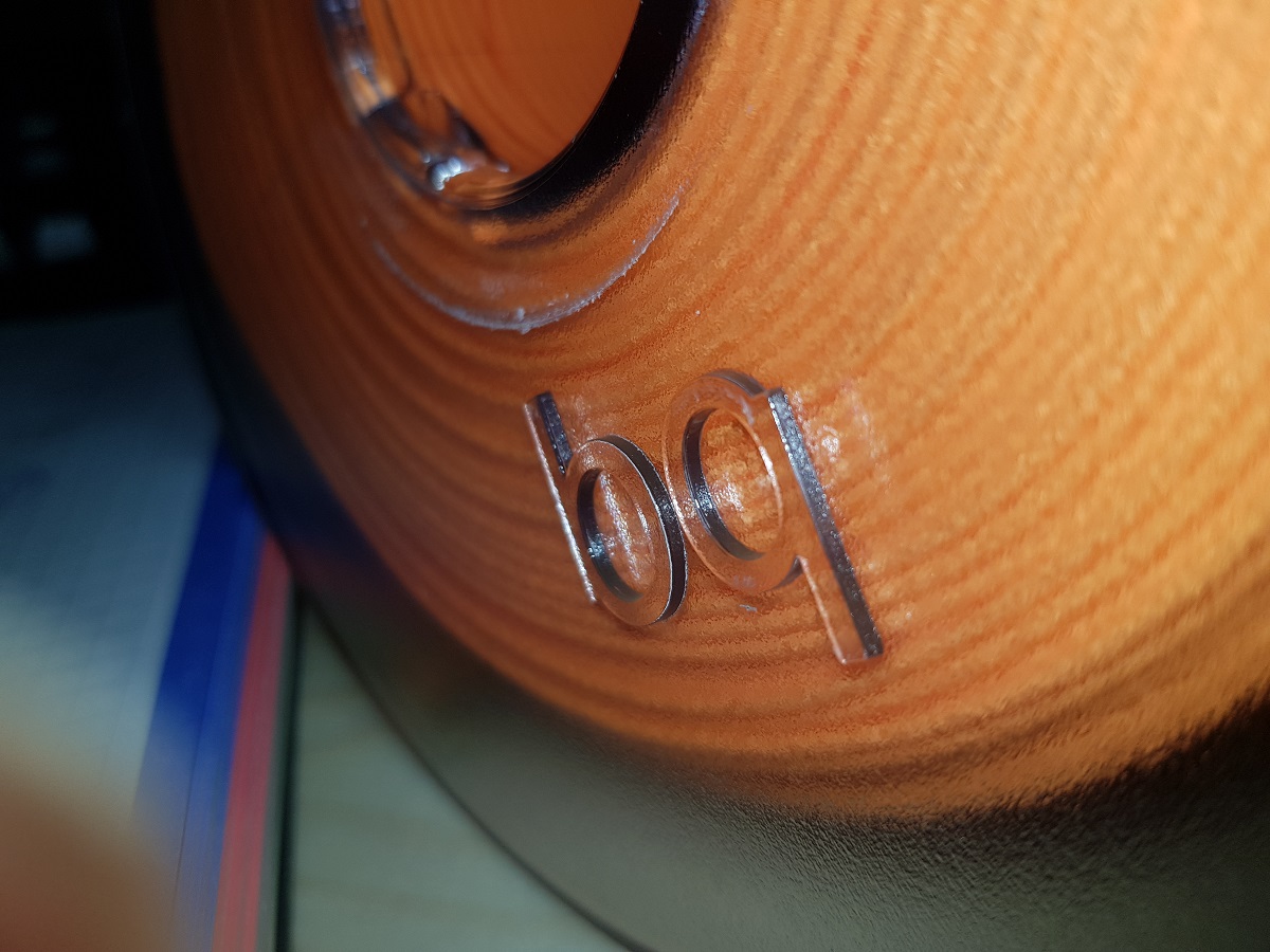
There is a big logo in one of the sides of the coil. It may occur that this logo gets stuck in the coil guide of the Ender 3.
BQ Logo in coil side
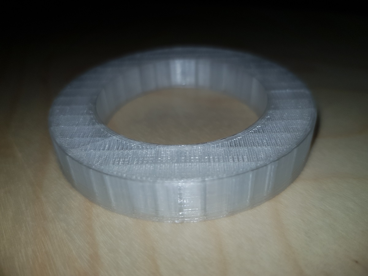
The easiest solution I found for this was printing a ring to prevent the coil from getting too close to the printer guide.
If you own a Creality Ender 3 and want to deploy Marlin on it you should first ask yourself why.
Why
When searching Google for that topic, a bunch of results and video tutorials appear in front of you talking about the ‘benefits’ of that ‘improvement’. Well, if you read the details you will find comments like Ender 3 is a great 3D printer but comes with some defects and the new version of Marlin is the solution to that. But seriously, what are those defects?
I bought the printer 3 weeks ago and I have to say that the results are impressive. Ok, it is my first 3D printer, but before acquiring it I was reading a lot about the subject and the most common advice in every web I visited was: don’t get frustrated about the results of 3D printing? You will get a lot of bad results and that’s normal. I’ve got too few bad results with my Ender 3… until yesterday.
Is it worthy?
After reading and watching some tutorials I decided to install a bootloader on my printer to upload the latest Marlin version to it. Why? I still don’t know.
Burning the Bootloader
It wasn’t easy. I look for some old Arduinos I knew I had and found a Duemilanove and a Mega. The board used by Creality in it’s Ender 3 is compatible with ATMega Sanguino boards, so all you have to do is burn the bootloader on the board and then use Arduino IDE to upload the sketch with the latest Marlin version.
Burning the bootloader has to be done with an ISP programmer or using an Arduino as ISP. The procedure is quite simple:
Open the board box of your Ender 3
Locate the ICSP connector
Use five Dupont Female to Female wires to connect:
GNDto GND
5V (VCC) to 5V(VCC)
SCKto SCK
MOSIto MOSI
MISOto MISO
Use one Dupont Female to Male wire to connect:
RESETto IO10 of your Arduino board
Upload Arduino ISP sketch to your Arduino (in examples)
Change board to Sanguinoand Programmer to Arduino as ISP
Burn Bootloader
I can’t remember how many times I tried. Changing port, reviewing wires many times, switching on / off, using Duemilanove and Mega… and nothing worked. I got the same error always and it seemed there was a problem getting synchronism in Avrdude tool.
Arduino’s ISP issue and the capacitor workaround
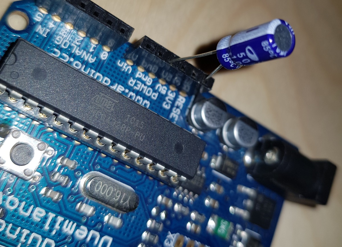
Then I remembered I had this problem years ago when playing with Arduinos. First Arduino models had problems with reset while negotiating ISP programming and the workaround is using a 10μF electrolytic capacitor between reset and GND pins.
The capacitor between RST and GND
Remember electrolytic capacitors have polarity and you shouldn’t reverse them:
After plugin the capacitor I was able to burn the uploader.
Uploading Marlin latest and ‘improved’ version
As expected, the printer was now reset. No printing program inside it and a blank LCD screen showing nothing.
That is the moment to upload Marlin latest software using Arduino IDE.
My intention is not telling you all the steps to do this, as the Internet is full of videos and tutorials (and remember, I don’t recommend doing it), but telling you what happened to my printer after doing that.
I uploaded the latest Marlin software with some miracle customizations performed in the parameters code by an expert guy. The result? After leveling the bed I tried with a small box and…
Filament not sticking to build plate
That was the first time in three weeks. Before that, the adhesion was very good. I tried some more times, I calibrated and leveled the bed and always the same result. I found that when the nozzle never got enough close to the plate. Maybe the miraculous customizations?.
I decided then to go back to the Creality version, which is a previous Marlin version adapted for Ender 3.
Creality Ender 3: Going back to manufacturer version
The good news is that we can now upload code to our printer because we have deployed a bootloader on it.
All we have to do is to find the manufacturer’s original code.
Locate the Marlin folder inside the folders created by the Unrar tool.
Copy the Marlin folder to a better location and edit the Configuration.h file.
Change the language for display. Locate the line (line #1188 in my version)
#define LCD_LANGUAGE cn
and replace cn with your language code (en, de, es, it, fr, …)
Compile and upload to the printer port detected when plugged in.
Remember you have to set these options in Tools menu:
Board: Sanguino
Processor: ATmega1284 or ATmega1284P (16MHz)
Port: The one detected by your machine.
Programmer: AVRISP mkll
Conclusion
I think it isn’t worthy of it deploying the latest Marlin version on your Ender 3, mainly because you are not going to get a lot of improvements.
In the other hand, it is very interesting having a bootloader installed and the capability of loading the code into the printer, but only if you need to customize the code.
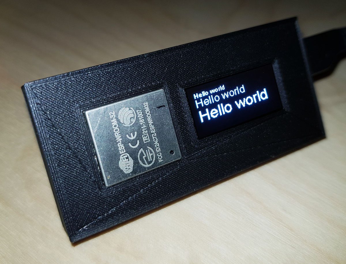
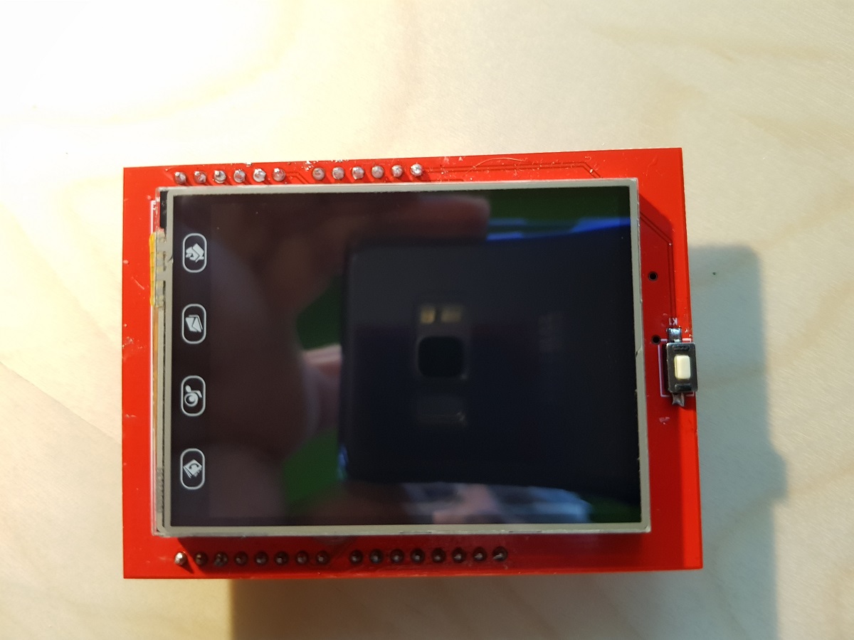
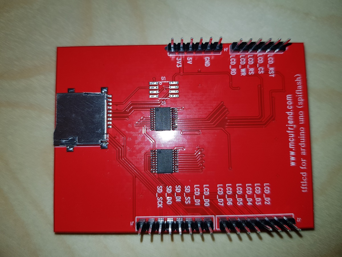
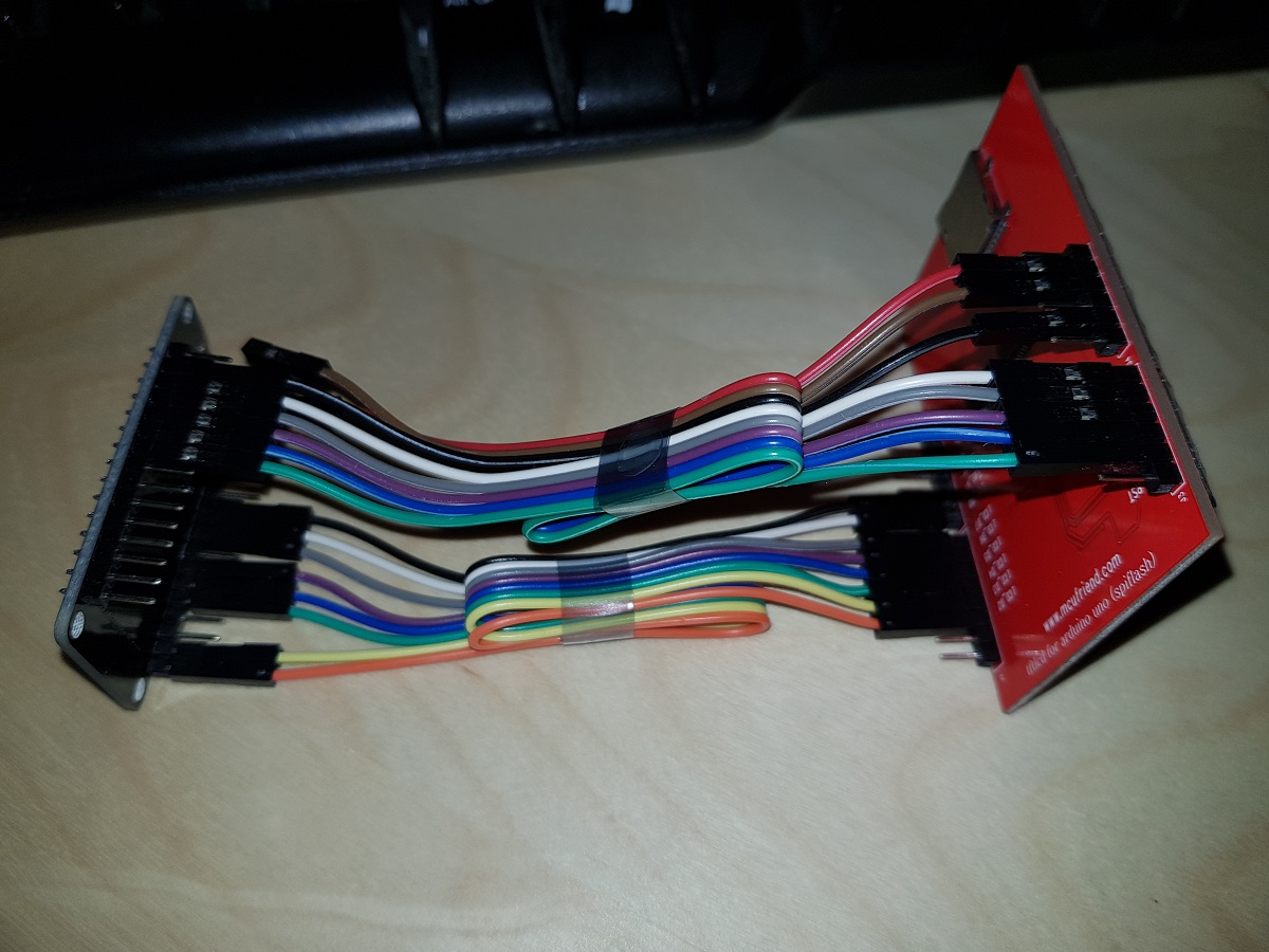
Today I’ve received two ILI9341 TFT screens that I ordered some weeks ago. These screens are in fact a shield designed for Arduino Uno but they work nicely when connected to other developer boards and the price is amazingly cheap: just US$4.
ILI9341 FrontILI9341 Back
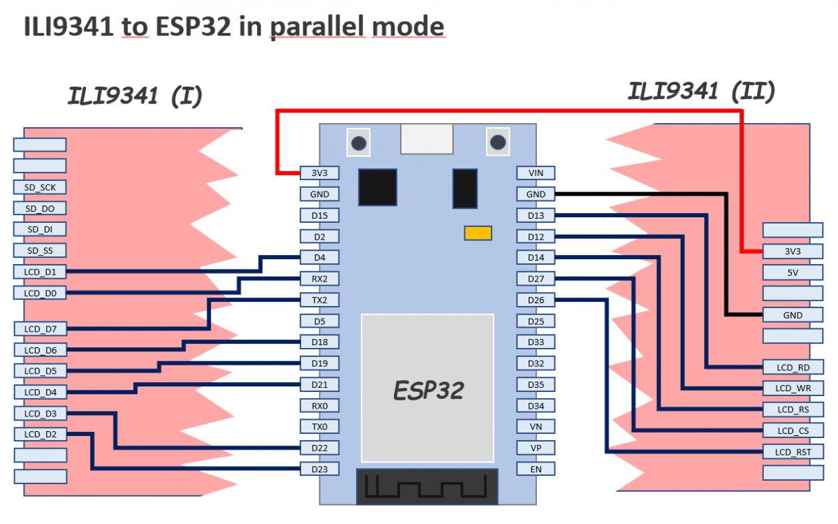
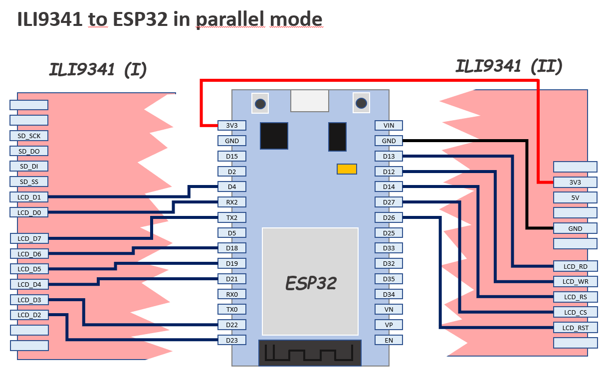
In this case, we will connect the screen to an ESP32 Dev Board.
The pins are configured in a slightly different way than other examples you could find in the web: I’ve tried to minimize mistakes because we will use 13 pins so I thought the best way would be to use as much as possible consecutive pins.
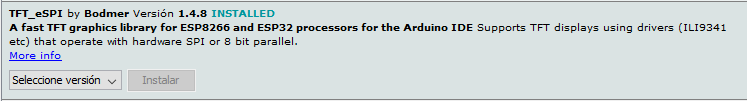
The library we will use is TFT_eSPI library by Bodmer and our only purpose by the moment will be executing an example demo script successfully.
During testing, you can connect TFT 3V3 pin directly to ESP32 3V3 pin, but do it only during a short period of time because the current drawn by the screen LEDs is 134mA and you will notice how the LEDs and the Development Board voltage limiter will become hot.
A 22Ω resistor (not 220) between the two 3V3 pins it’s enough to reduce the current to 23mA and though the screen is not the brightest one in the world I think it is enough for testing purposes.
Once you have finished the connection of the pins as described in the diagram above, you can install the TFT_eSPI library if you don’t have it already installed.
Open Arduino IDE, go to Library Manager and in the search box type TFT_eSPI. In the results list, look for the next and install it.
TFT_eSPI Bodmer Library for Arduino
Now you have the library installed you have to configure the IO pins where we have connected our screen. Other libraries use the definition of constants at the top of each sketch to do this, but TFT_eSPI uses a common file to define the configuration.
Find in your Arduino installation the file called User_Setup.h
It should be located in a path equivalent to this:
[Arduino Folder]/libraries/TFT_eSPI/User_Setup.h
Now, copy the file for backup purposes and edit the original to place inside it this following content (replacing all the previous content):
// See SetupX_Template.h for all options available

#define ESP32_PARALLEL


#define ILI9341_DRIVER


// ESP32 pins used for the parallel interface TFT
#define TFT_CS   27  // Chip select control pin
#define TFT_DC   14  // Data Command control pin - must use a pin in the range 0-31
#define TFT_RST  26  // Reset pin

#define TFT_WR   12  // Write strobe control pin - must use a pin in the range 0-31
#define TFT_RD   13

#define TFT_D0   16  // Must use pins in the range 0-31 for the data bus
#define TFT_D1   4  // so a single register write sets/clears all bits
#define TFT_D2   23
#define TFT_D3   22
#define TFT_D4   21
#define TFT_D5   19
#define TFT_D6   18
#define TFT_D7   17


#define LOAD_GLCD   // Font 1. Original Adafruit 8 pixel font needs ~1820 bytes in FLASH
#define LOAD_FONT2  // Font 2. Small 16 pixel high font, needs ~3534 bytes in FLASH, 96 characters
#define LOAD_FONT4  // Font 4. Medium 26 pixel high font, needs ~5848 bytes in FLASH, 96 characters
#define LOAD_FONT6  // Font 6. Large 48 pixel font, needs ~2666 bytes in FLASH, only characters 1234567890:-.apm
#define LOAD_FONT7  // Font 7. 7 segment 48 pixel font, needs ~2438 bytes in FLASH, only characters 1234567890:.
#define LOAD_FONT8  // Font 8. Large 75 pixel font needs ~3256 bytes in FLASH, only characters 1234567890:-.
#define LOAD_GFXFF  // FreeFonts. Include access to the 48 Adafruit_GFX free fonts FF1 to FF48 and custom fonts

#define SMOOTH_FONT
Save the file and go back to Arduino IDE.
Open the example sketch UTFT_demo (it is under File / Examples / TFT_eSPI / 320 x 240 / UTFT_demo)
At this point, you can compile and upload the sketch to your ESP32. If everything went ok you should see some graphics, backgrounds and texts appearing in your TFT screen. Otherwise please review carefully the IO pins configuration (hard and soft).
If it works, probably you’ll see the results like in a mirror. To solve this, go to the sketch and edit the line that sets the screen orientation. This is done in the setup function.
void setup()
{
  randomSeed(analogRead(A0));
// Setup the LCD
  myGLCD.init();
  //myGLCD.setRotation(1); //Comment out this one and insert the one below
  myGLCD.setRotation(7);
}
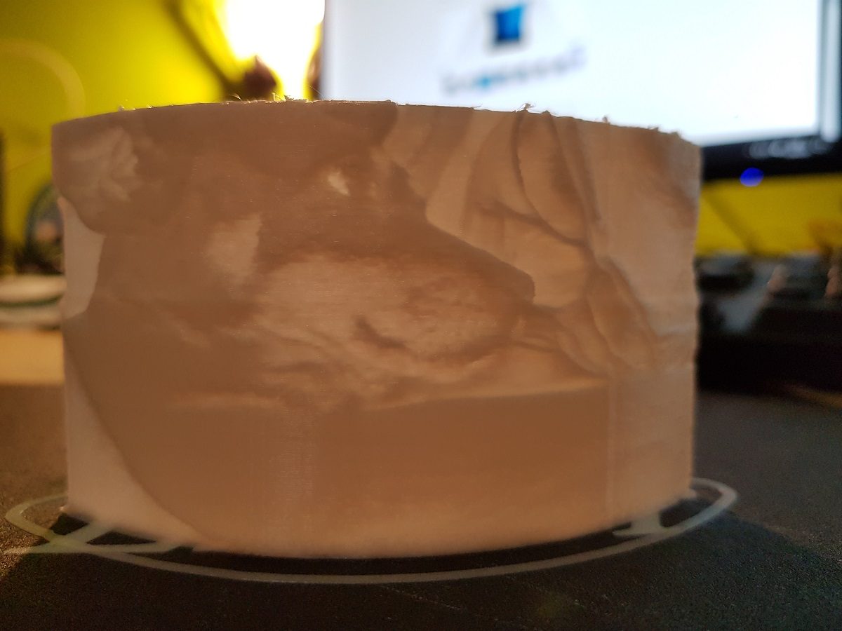
A lithophane (French: lithophanie) is an etched or molded artwork in very thin translucentporcelain that can only be seen clearly when back lit with a light source.
If we put a light in the back of a translucent sheet, depending on the thickness of the sheet it will appear lighter (when thin) or darker (when thick).
Getting a picture and making some calculations it could be possible to create a 3D printed object of different thickness at the points where we want to make the light darker or lighter to reproduce the original picture.
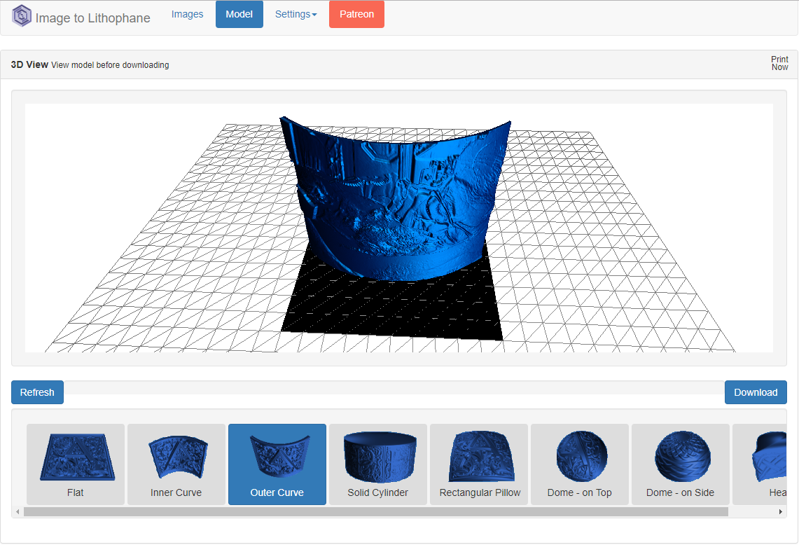
That’s what Image to lithophane does. By uploading a picture it makes all the work for us and let us download a .stl file to print the figure.
As this has been the first time I’ve tested it, I’ve first converted the picture to Black & White so I can manually adjust brightness and contrast and then uploaded the .jpg to the web.
My family in B/W
The web is plenty of options and parameters, but it is very intuitive and it is easy to choose the model we want to create from our picture. Take care of the option Settings / Image settings / Positive – Negative. If your picture is not inverted use Positive option.
Model created by the application
After downloading the .stl file, I prepared it with Cura taking care of filling (100% fill) and of course using white filament.
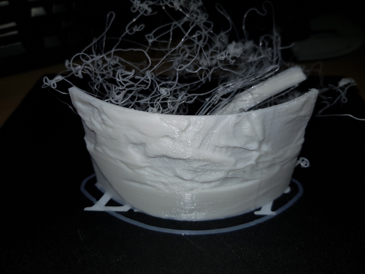
Though the figure is not very large (about 10cm width) it takes a long time to be finished (right now 17% and spent 30 minutes).
Printing… Waiting… Printing… and two and a half hours later… disaster!
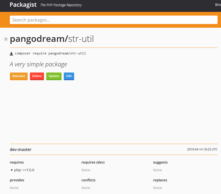
If you are reading this I guess you know what Composer and Packagist are and probably you need to know how to build your own package or you just simply don’t remember all the steps to do it.
Otherwise, you can get some very basic info of Composer here: Wikipedia Composer and if you want to dive into the documentation then you can visit Composer Documentation page. Packagist is the main repository for Composer packages.
Preparation
We will create a package and before writing a line of code, we will compile some basic information. I’m using mine as an example.
Developer name / Organization: pangodream
Package name: str-util
Description: A very simple package
Setting up the project for the package
Create the project folder
In our case, the project folder will be str-util
Create two more folders inside the project one; one for the package code and the other one for testing. The folder structure should be:
str-util
    /src
    /test
Create composer.json file
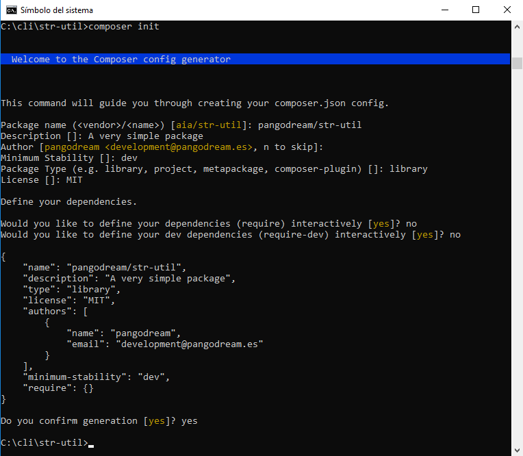
Access the project folder and create composer.json by typing
> composer init
Composer will try to guess some of the configuration values
Once we confirm the file generation, a composer.json file will be in our project folder and it will contain some very similar to this:
So, this is now the content of our project folder:
str-util
    composer.json
    /src
    /test
Edit to complete composer.json
We will add some information about autoloading (“autoload”) and also tell composer our dependencies (“require”). For instance, which is the minimum version of PHP that our library needs to work.
Inside the composer.json file, we told composer the path were StrUtil package classes are. So, each time we reference in our code a class qualified with its package name Composer will look into the composer.json file to know where that class file is.
In our case, the package name is StrUtil and the class is Counter (because our class will contain some methods to count words, paragraphs, letters, …).
Inside src folder, let’s create a new folder for our package with the name we gave it inside composer.json: StrUtil, and inside that folder, we will place one of our package classes file. Now, we have this folder hierarchy
/str-util
    /src
        /StrUtil
            /Counter.php
So, when PHP finds a reference to a class with the ‘use’, it will look into composer.json. For instance, let’s say we have a line of code like this
use StrUtil\Counter;
What composer.json file indicates is that StrUtil package is under src folder
"autoload": {
        "psr-0": {
            "StrUtil": "src/"
        }
    }
So, the Counter.php file containing the Counter class code should be located in
src/StrUtil/Counter.php
Now we know how the class file is located and loaded, let’s write down the code:
<?php
/**
 * Created by Pangodream.
 * Date: 14/04/2019
 * Time: 18:50
 */

namespace StrUtil;


class Counter
{
    /**
     * @param string $text The text we want to count the number of words it consist of
     * @return int The number of words in text
     */
    public static function countWords(string $text){
        /** @var int $count To store the result of counting words in text */
        $count = 0;
        //Clean up the string
        $text = trim($text);
        /** @var array $words Array containing the words */
        $words = explode(" ", $text);
        //Array size is the number of words in text
        $count = sizeof($words);
        return $count;
    }
}
And now we know how to reference that class, let’s create a test file to verify that our class works. We will name this file testStrUtil.php and save it inside the test folder we created before:
str-util
    /test
        /testStrUtil.php
<?php
/**
 * Created by Pangodream.
 * Date: 14/04/2019
 * Time: 19:03
 */

//Use composer autoload to load class files
require_once __DIR__ . "/../vendor/autoload.php";

//Required package/libraries
use StrUtil\Counter;

$text = "Aequam memento rebus in arduis servare mentem";
$wordCount = Counter::countWords($text);
echo "The txt contains ".$wordCount." word(s)\r\n";
Testing our package
From the str-util folder, we are going to invoke the test PHP file and see what happens:
str-util> php test/testStrUtil.php
The text contains 7 word(s)
Our package containing only a class is working and now we are ready to publish it.
Repository part: github.com
The next thing we’ll do is creating a new repository with our GitHub account.
Create the repository at github.com
Go to github.com and create a new repository called str-util. It is a good practice to give a repository description and also initialize with a README file. Because you are going to share the package in packagist.org you need to Add a license file, in our case an MIT License.
Add package files to the repository
Now we will make an initial commit to our repository with the files we already have created inside the src folder.
From the str-util folder, execute the following commands:
---->str-util> git init
Initialized empty Git repository in C:/cli/str-util/.git/

---->str-util> git add src
---->str-util> git add composer.json

---->str-util> git commit -m "Initial commit"
[master (root-commit) af7bbac] Initial commit
 2 file changed, 28 insertions(+)
 create mode 100644 src/StrUtil/Counter.php
 create mode 100644 composer.json

---->str-util> git remote add origin https://github.com/YOUR_USER_NAME/str-util.git

---->str-util> git pull origin master --allow-unrelated-histories
From https://github.com/YOUR_USER_NAME/str-util
 * branch            master     -> FETCH_HEAD
Merge made by the 'recursive' strategy.
 README.md | 2 ++
 1 file changed, 2 insertions(+)
 create mode 100644 README.md

---->str-util> git push origin master
fatal: HttpRequestException encountered.
   Error al enviar la solicitud.
Username for 'https://github.com': YOUR_USER_NAME
Password for 'https://YOUR_USER_NAME@github.com':
Counting objects: 7, done.
Delta compression using up to 4 threads.
Compressing objects: 100% (4/4), done.
Writing objects: 100% (7/7), 928 bytes | 309.00 KiB/s, done.
Total 7 (delta 0), reused 0 (delta 0)
To https://github.com/YOUR_USER_NAME/str-util.git
   16f9ce1..8f91cfa  master -> master
Let’s analyze what we have done:
git init
Initialize the Git repository in our local directory. Git will create its hidden files to control operations made on the repository.
git add src

git add composer.json
We are telling Git which files we want to add to the repository. In our case only the src folder and the composer.json file will be synchronized, the rest of the files will stay only in our local machine.
git commit -m "Initial commit"
Our first Initial commit to our local instance of the repository. We haven’t sent anything to github.com until now.
Now we will add an origin (origin means remote repository) to our local repository. This is the reference to our github.com repository. Replace YOUR_USER_NAME with your own Github user name.
If at this point we try to push (send to remote) the commit we made locally, an error will occur because in the remote instance of the repository there are files that don’t exist locally (README file for instance). We cannot send and receive at the same time under normal circumstances, so we will first pull files from origin ignoring possible conflicts:
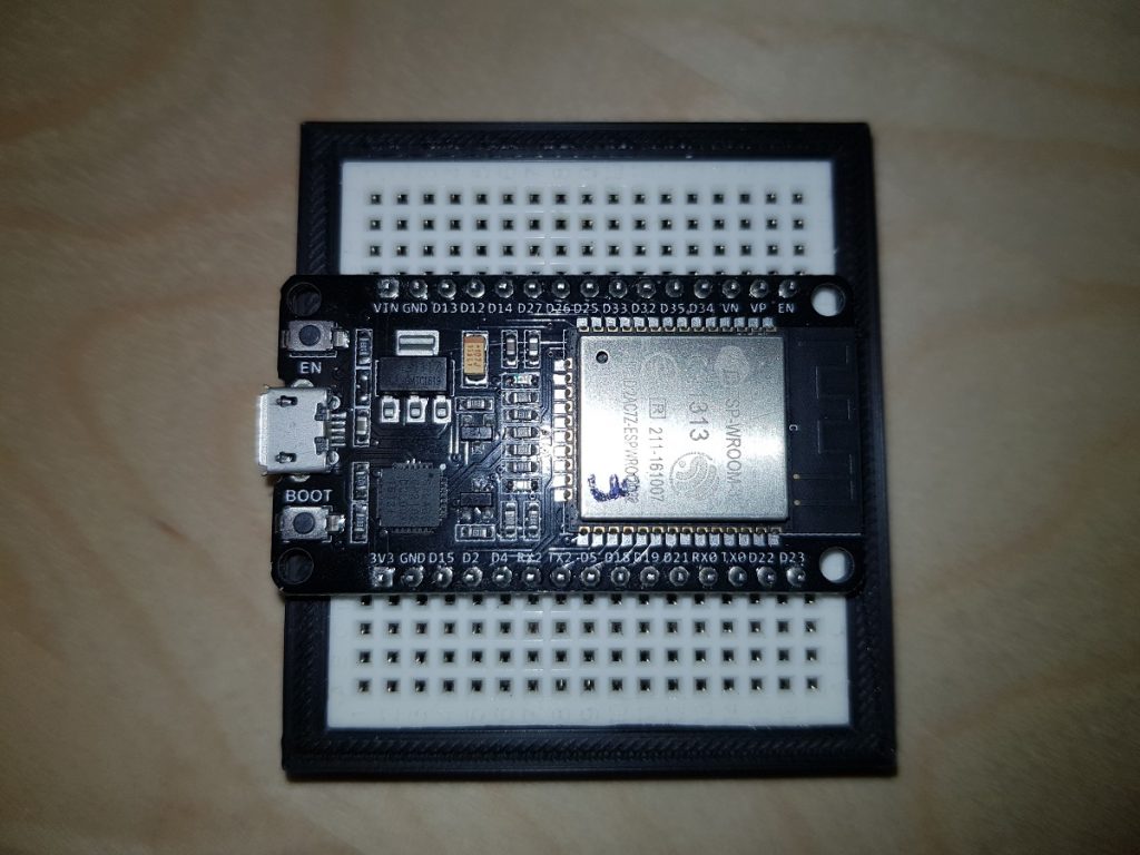
It is frustrating the first time you insert an ESP32 dev board into a breadboard and you notice there’s no room for wires.
ESP Dev Board on Breadboard
What I usually do is putting a breadboard aside another one, but I don’t like it very much.
Workaround for ESP Dev Board on two breadboards
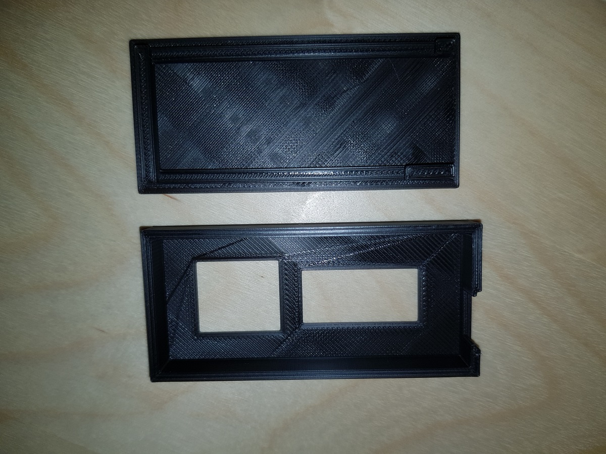
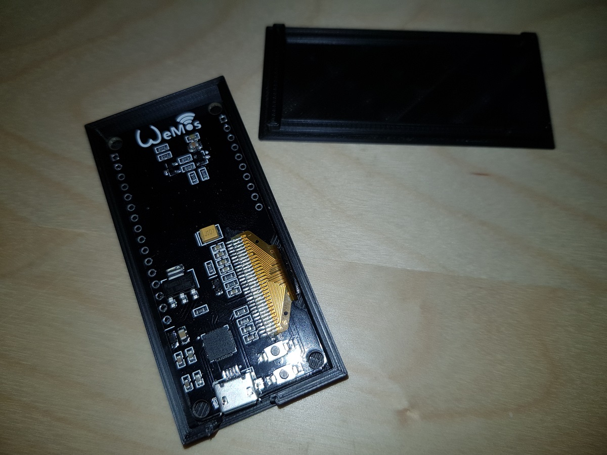
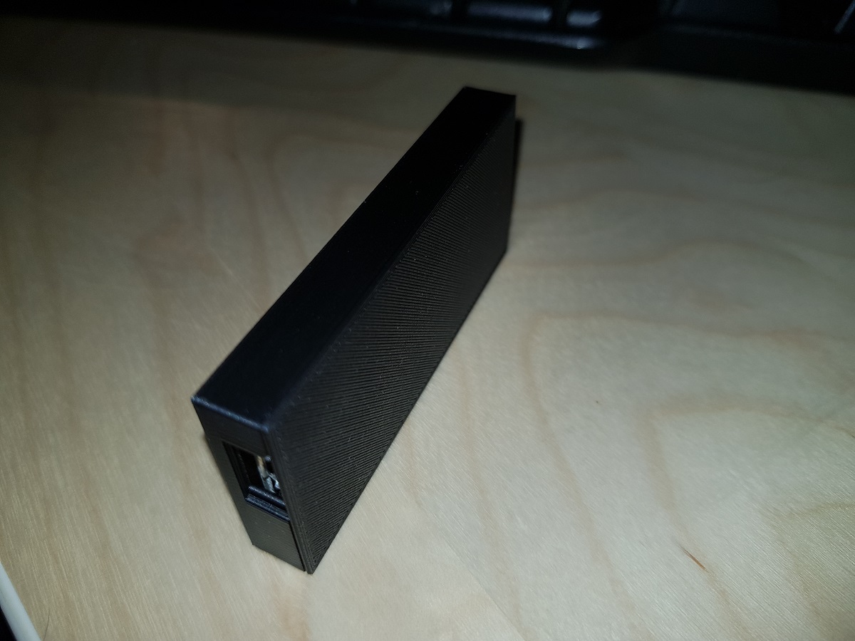
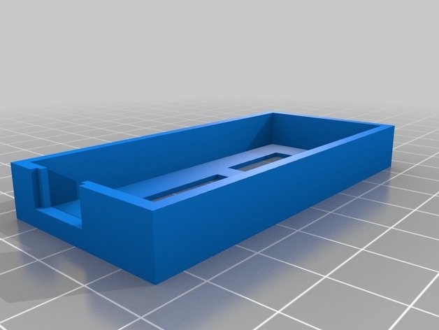
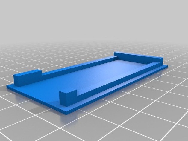
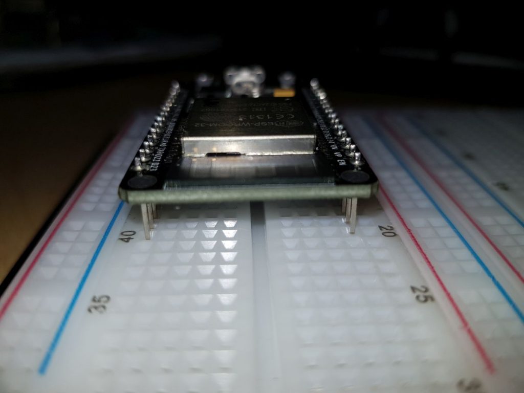
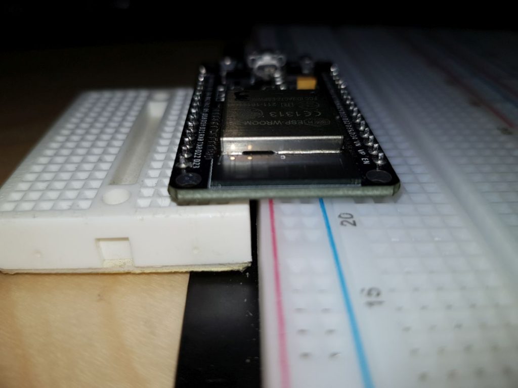
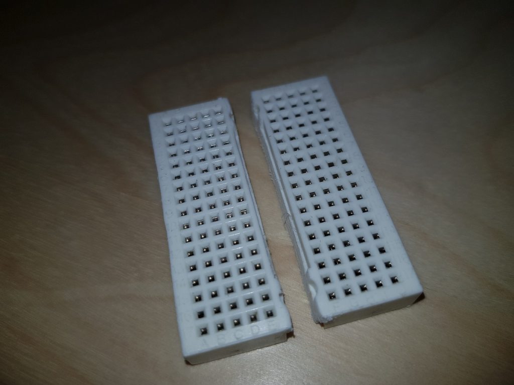
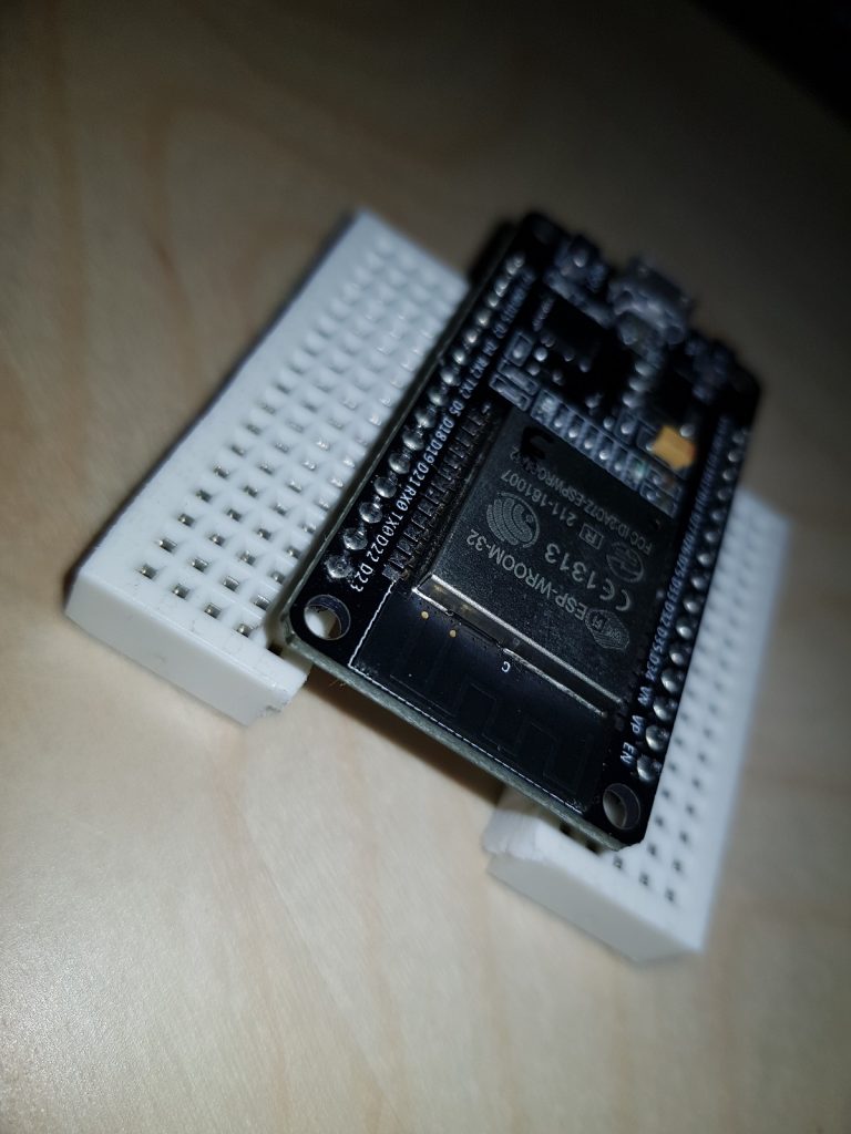
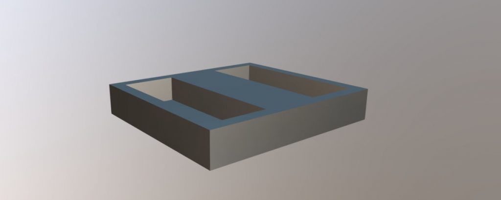
I decided then to split the small board into two pieces and insert them in a 3D printed base so that the dev board pins get into the first row of holes and the rest remain available.
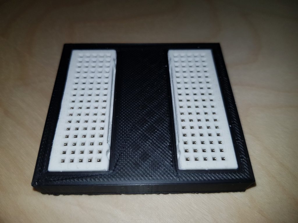
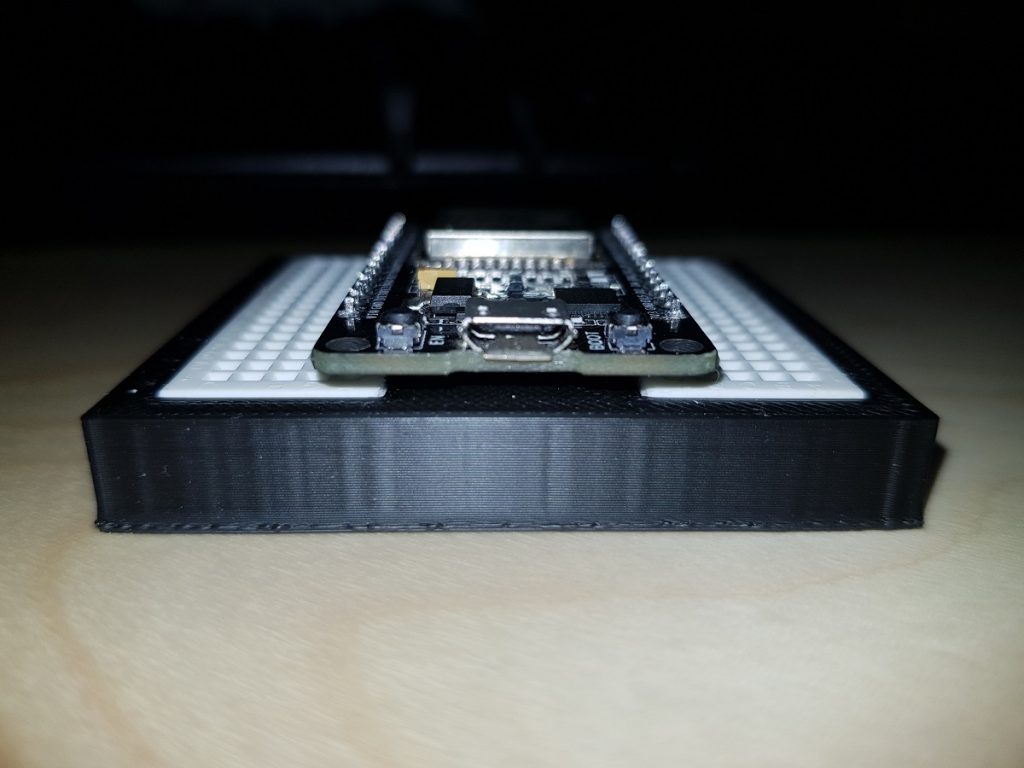
Split breadboardESP32 Dev Board on the split breadboardBreadboard splitter
Breadboard SplitterBreadboard Splitter side viewBreadboard Splitter top view
This website uses cookies to improve your experience. We'll assume you're ok with this, but you can opt-out if you wish.AcceptReject
Privacy & Cookies Policy
Privacy Overview
This website uses cookies to improve your experience while you navigate through the website. Out of these, the cookies that are categorized as necessary are stored on your browser as they are essential for the working of basic functionalities of the website. We also use third-party cookies that help us analyze and understand how you use this website. These cookies will be stored in your browser only with your consent. You also have the option to opt-out of these cookies. But opting out of some of these cookies may affect your browsing experience.
Necessary cookies are absolutely essential for the website to function properly. This category only includes cookies that ensures basic functionalities and security features of the website. These cookies do not store any personal information.
Any cookies that may not be particularly necessary for the website to function and is used specifically to collect user personal data via analytics, ads, other embedded contents are termed as non-necessary cookies. It is mandatory to procure user consent prior to running these cookies on your website.