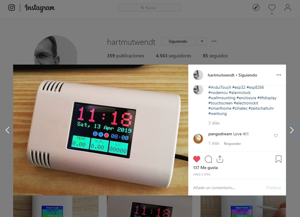
Hackaday.com made my day

Since I was a child I loved gadgets, electronic parts, wires, opening every machine that fell into my hands.

My job is related to technology, but nothing of hardware in it, just software. I work for an advertising company and we don’t produce anything you can touch with your hands. Though I am an enthusiast of coding and designing software I am always buying cheap components, electrical instrumentation and from time to time I ‘produce’ some little things for the home, but I never have enough time to make interesting things. 

During years I have been reading blog entries at hackaday.com. The things they talk about are those things I would love to be making the whole day.

Some months ago I started walking with pain in one of my feet. Things became more complicated and finally, I had surgery and had to stay at home during some months. That means a big issue for me because of my job but as someone said “problems can become opportunities” and that’s what it happened… now I have a bunch of time to think and study.

As I had a lot of components waiting for me, I decided to buy a 3D printer and make something. Three weeks ago I started thinking on an Alarm Clock and today that thing is Claudio.

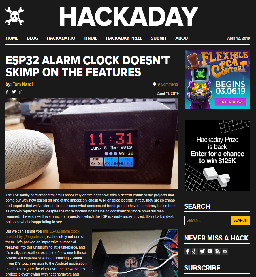
Some days ago I submitted the Github repository link to hackaday.com thinking they would ignore it but they replied my email and told me their intention to publish a post about it. I felt really proud and happy. 

Today they made my day. Thanks, Tom! 😀

Hackaday post about Claudio

Claudio, the box

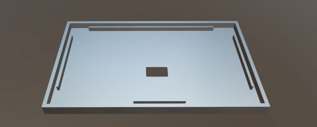
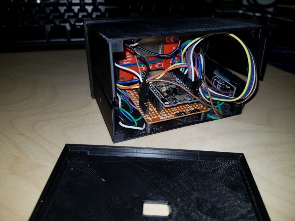
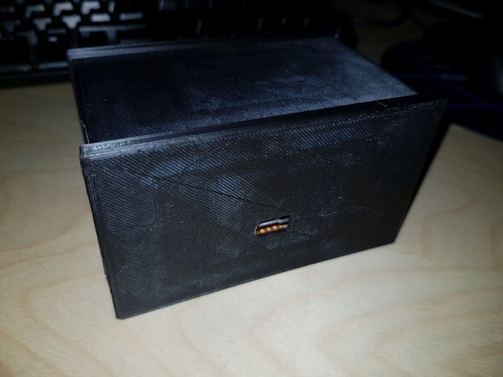
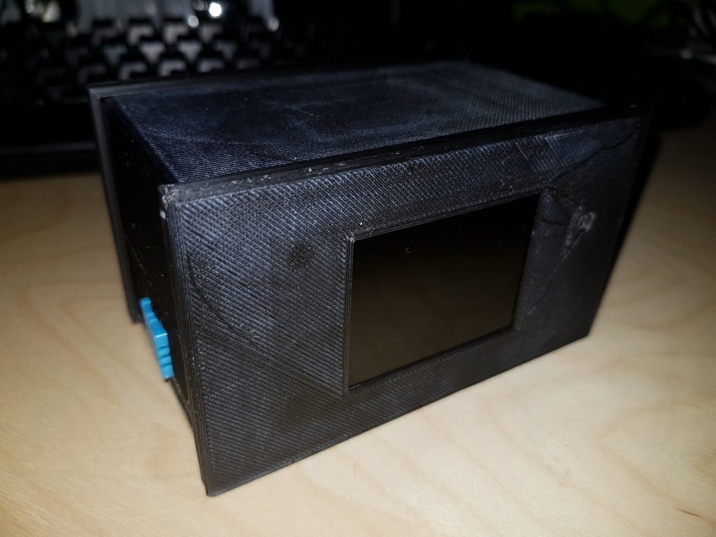
The box of the prototype consists of 4 pieces designed with Freecad to be 3D printed.

I used PLA, heating the bed up to 60ºC and the nozzle to 200ºC.

Claudio Front side
Frontside (from inside view)
Base (from inside view)
Cover (upside down)
Backside (from inside view)

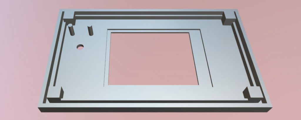
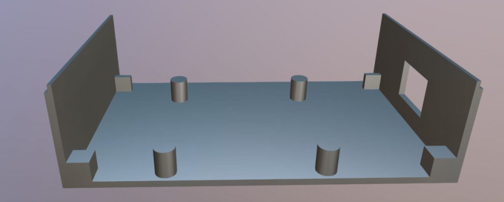
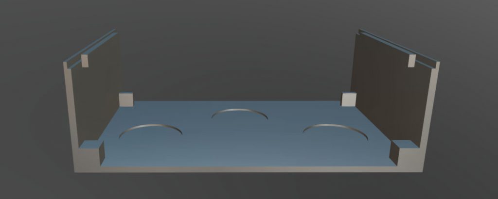
Mounting is very simple and though the design includes eight blocks at the corners to allow screwing I found it wasn’t necessary as the pieces stay together after mounting due to pressure.

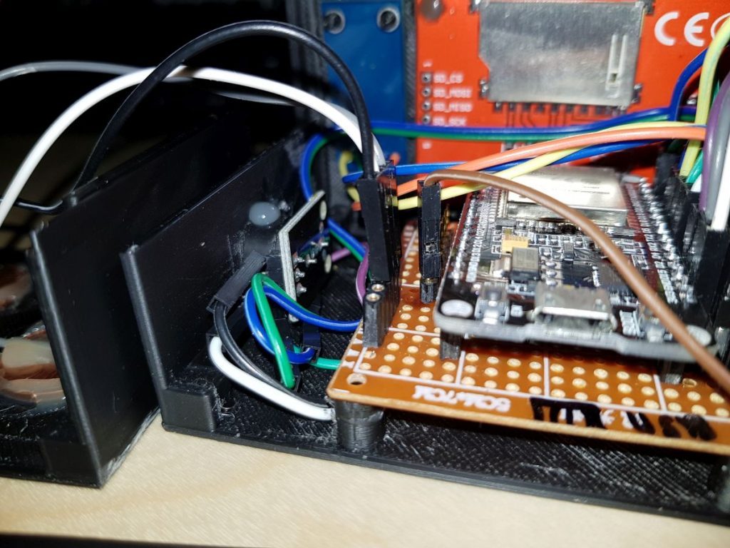
The four ‘columns’ at the base allow mounting a PCB over them and some wires can pass down it.

Some more pictures follow below:

Buzzer placement

DHT11 placement


MicroUSB hole
Mounted box


Claudio, parts and some links

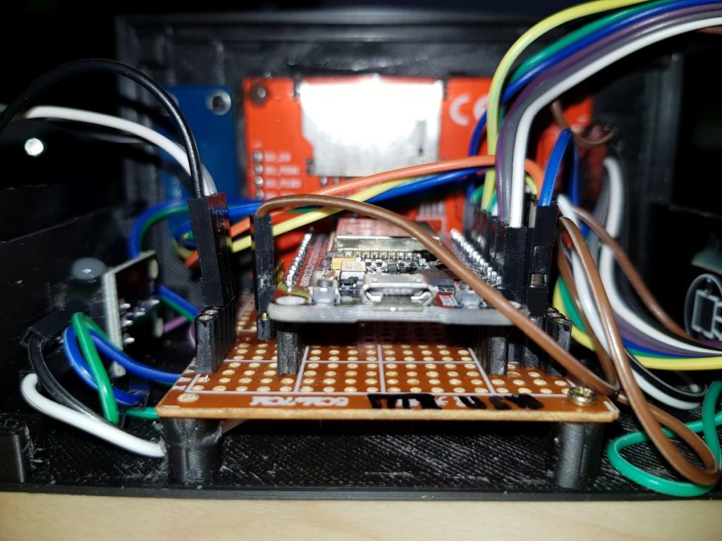
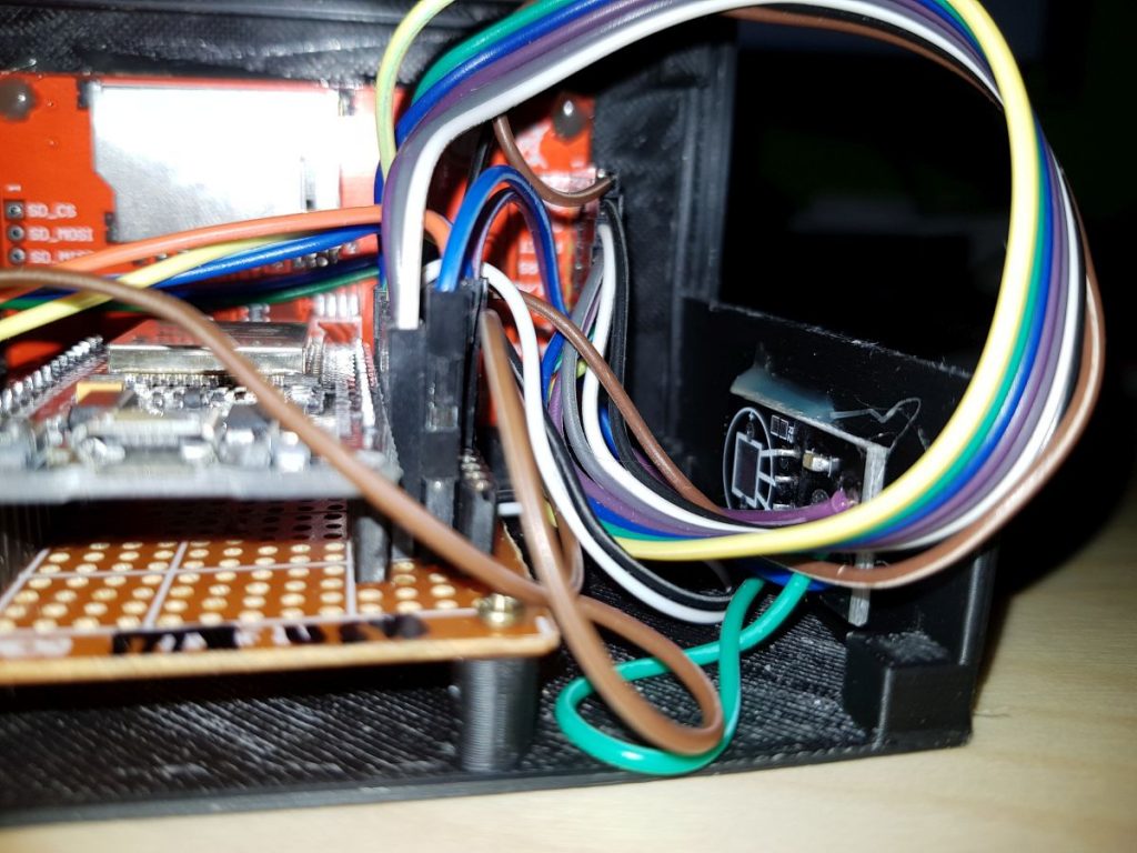
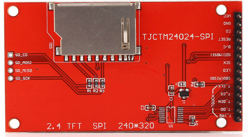
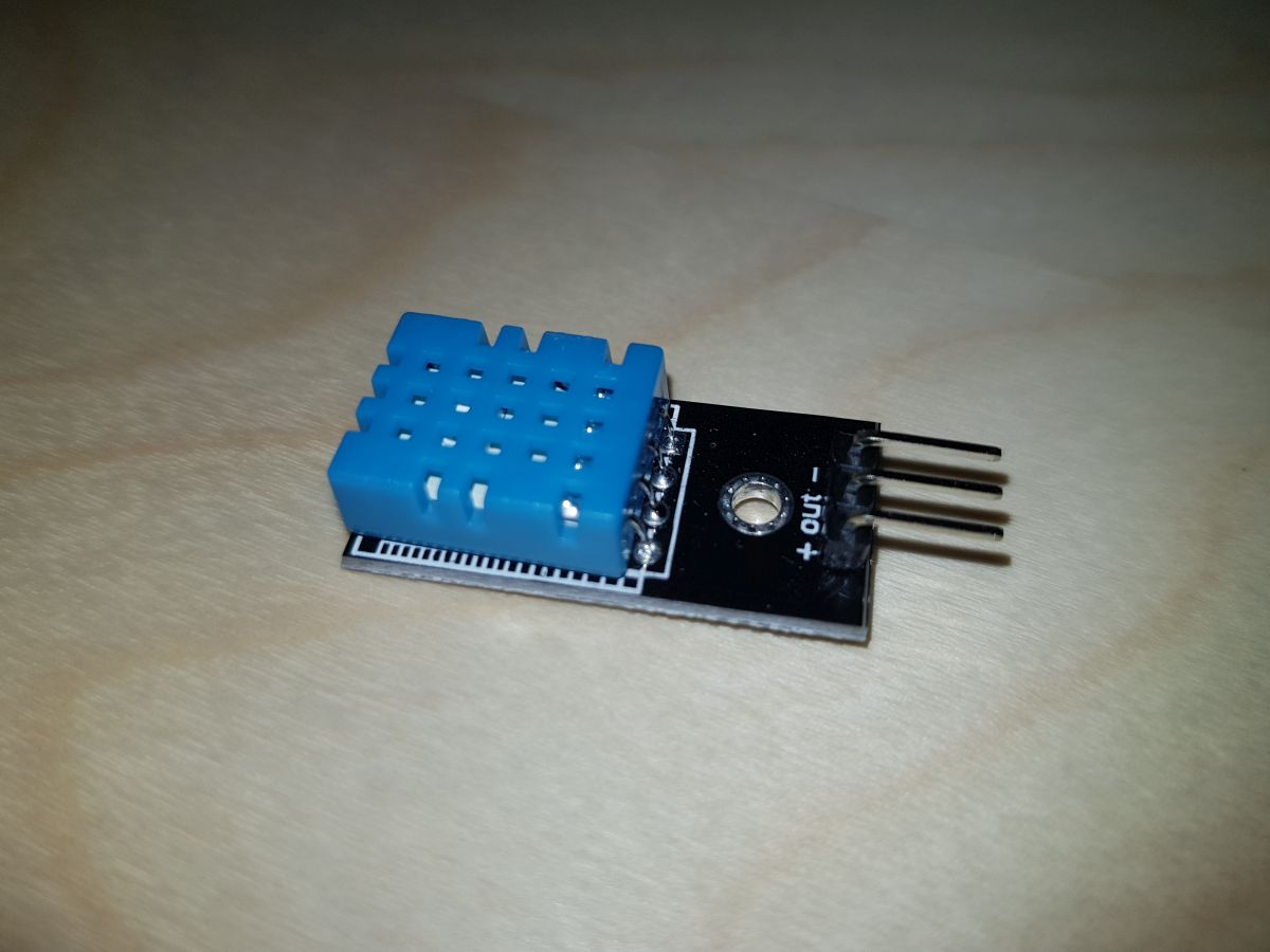
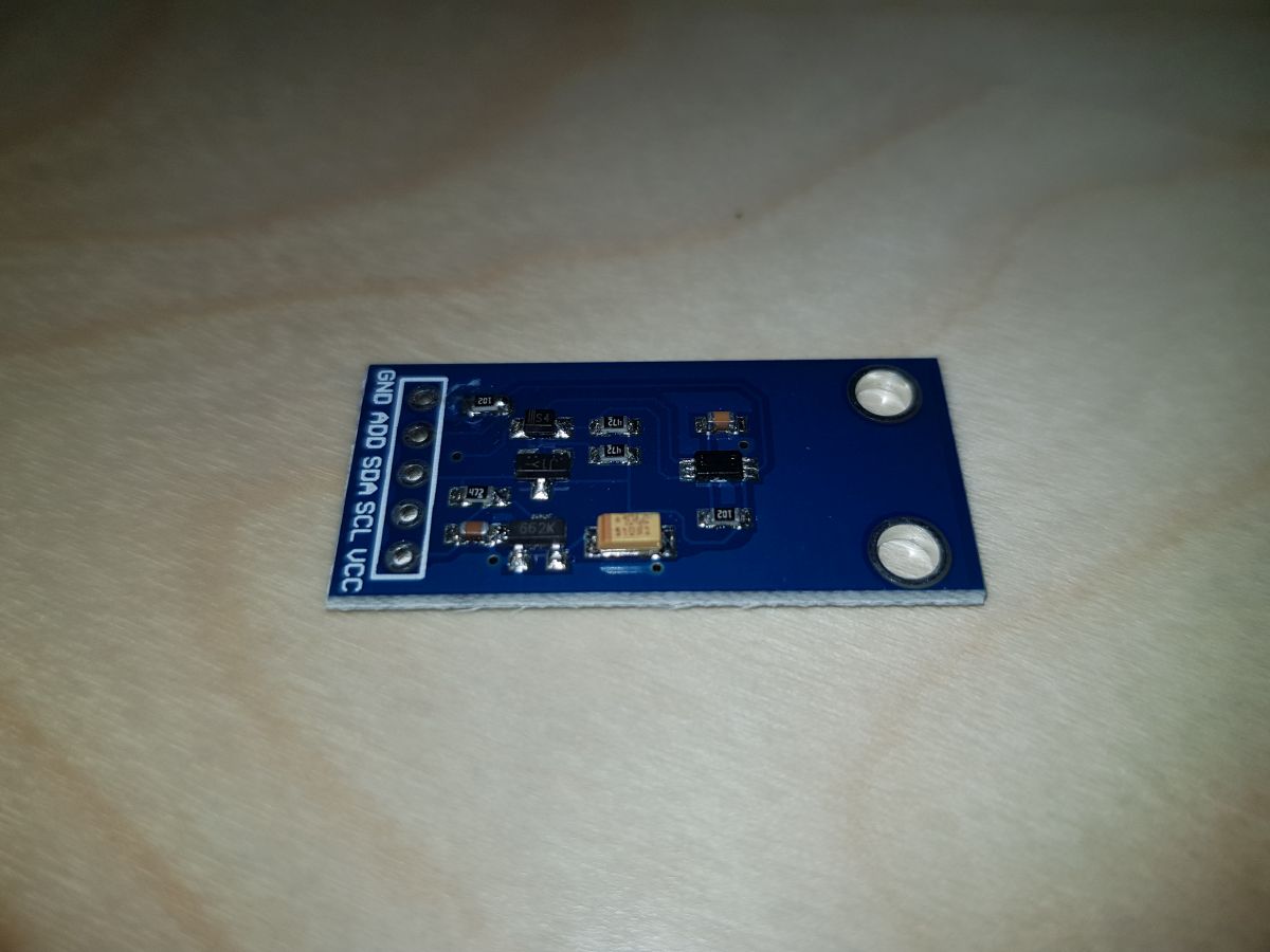
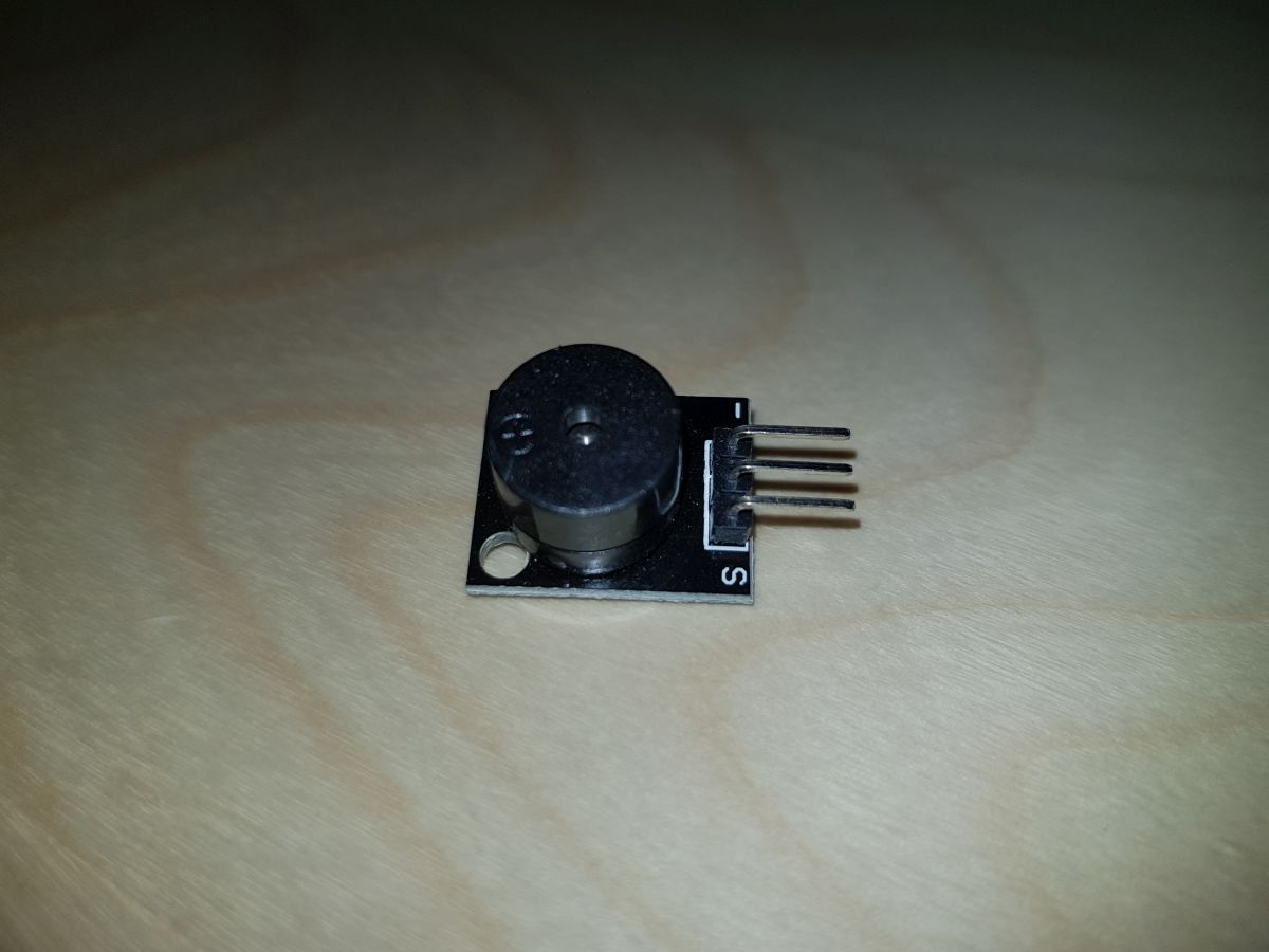
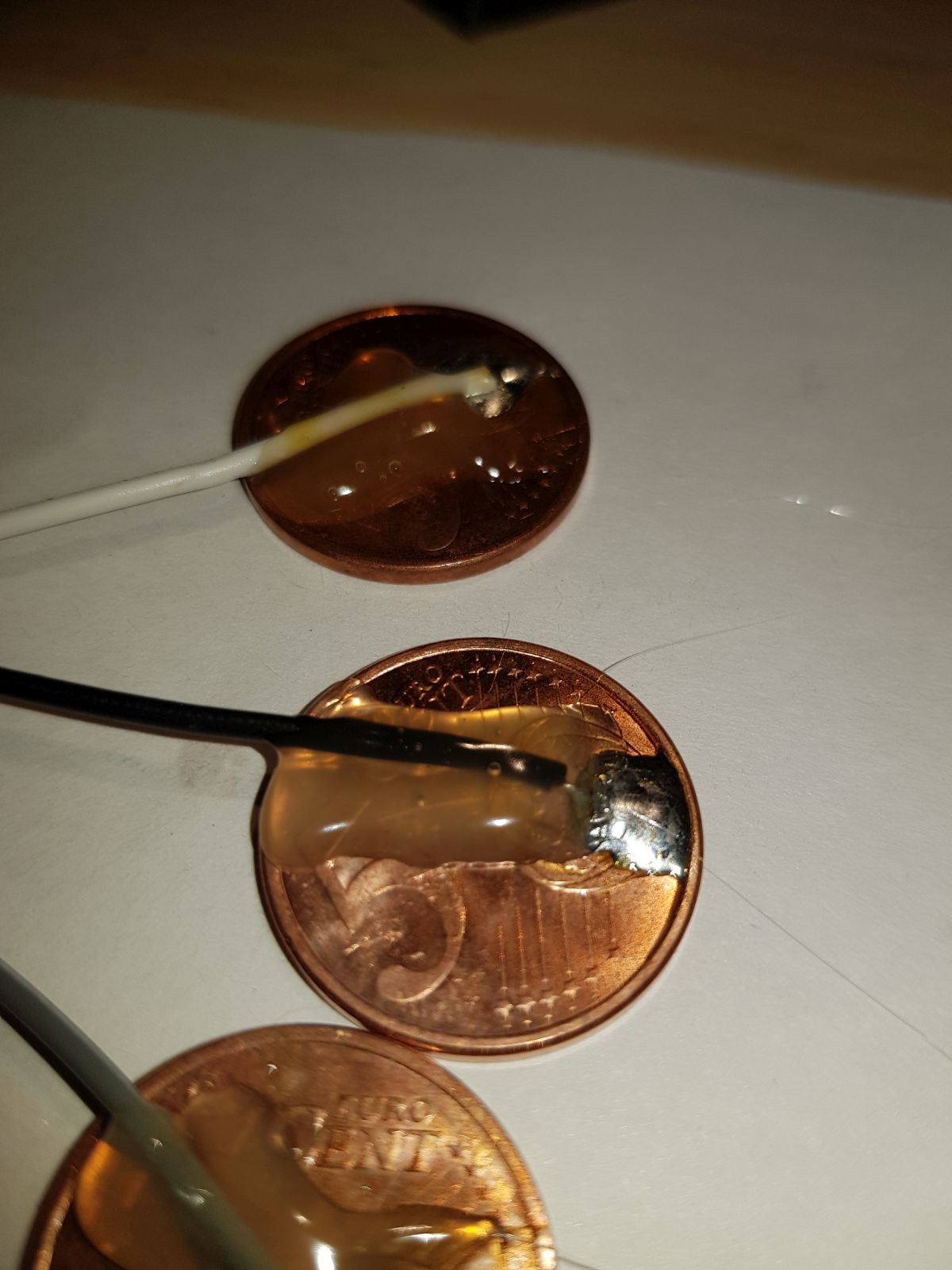
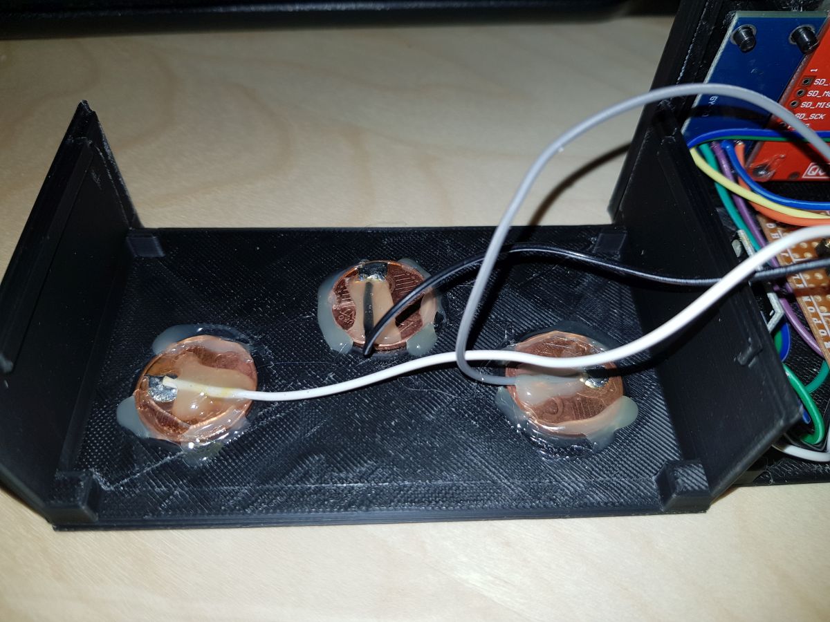
Claudio consists of just five (or six) components, the wiring between them and code. No resistors, capacitors, diodes… no discrete components apart from 3 five cents of € coins. 😉

List of components:

  1. ESP32 Development Board: I’ve tested two different boards, and though they are very similar the results were not the same. 
    ESP32 Development Boards Front
    ESP32 Development Boards Front

    ESP32 Development Boards Back
    ESP32 Development Boards Back

    Price: US $7
    The first one was the one on the right side. It is a board I bought a year ago and it was working fine (for small tests) since then. When I first tried to put all the components together I noticed that ILI9341 TFT Display and WiFi connection were not good friends working at the same time. After 3 or 4 display operations (text, area fill, …) the screen went always blank and only when WiFi library was loaded. I tried multiple pin configurations, alternate libraries loading order. I tested voltage on each significant pin (D/C, CLOCK, MOSI) and no result.
    Finally, I decided to give a try one of the last boards I bought: the model on the left side. The result was successful. No blank screen. But, these boards have a bug design: they don’t allow uploading schemas directly from Arduino IDE (Error: Timed out waiting for packet header) and you have to ‘play’ with EN and BOOT buttons every time.
    Workaround: once Arduino IDE tries to upload the schema, press BOOT and without releasing it press also EN button, wait for a half second, release EN and when IDE stops waiting and starts the uploading you can release BOOT button.

    Error Time_out_waiting_for_packet_header
    Error uploading schema from Arduino IDE

    ebay.com search for ESP32 Dev Board
  2. ILI9341TFT Screen – SPI
    Again, the component I had at home was about one year old. The only difference is that the one you can find now implements a set of pins to control a touch panel (though they say at the product description “non-touch”). Anyway, I think the one is being sold now is perfectly compatible with the previous model.
    What we need for this design is a model with an SPI pin configuration. Sellers usually refer to these as “driven with at least four IO”
    Price: US $7
    ILI9341 SPI TFT Display
    ILI9341 SPI TFT Display
     Sample ebay.com link to ILI9341

  3. DHT-11 Temperature and Humidity Sensor
    This is a low-cost sensor very easy to use. Though it has four pins, only three of them have a function (the other one is not connected).
    Simply connect ground pin to GND, VCC pin to 3V3 and Data Out pin to any ESP32 IO pin.
    Depending on the range of temperature/humidity you need to measure, you should take a look also to DHT-22 sensor (which implements a wider range and more accuracy), but in my case, 0-50ºC/20-80%R.H. is quite enough.
    Price: US $1
    DHT-110 Temperature and Relative Humidity sensor

    ebay.com link to DHT11 search

  4. BH1750FVI Digital Light Intensity Sensor
    I think the best feature of this sensor is, apart from ease of use, the sensibility and stability.
    It measures ambient light and gives the result in Lux
    It has 5 pins, but once again we can ignore one of them (ADD) by connecting it to GND. So, we only need two ESP32 IO pins to connect  SDA and SCL sensor pins.
    GND and VCC pins go to GND and 3V3 ESP32 pins respectively.
    Price: US $1
    BH1750FVI Ambient Light Sensor
    BH1750FVI Ambient Light Sensor
    ebay.com link to BH1750FVI search

  5. Passive Piezo Buzzer
    The most basic part of the system.
    Just two pins (the middle one can be ignored), one goes to GND and the other one to an ESP32 IO pin.
    Price: US $0.2
    Passive Piezo Buzzer
    Passive Piezo Buzzer

    ebay.com link to Piezo Buzzer search

  6. Touch sensors (5 cents of € coins)
    Each one connected to an ESP32 Touch pin.
    Price: 0.15€
    5 cents euro coin
    5 cents euro coin
    Mounted coin touch sensors
    Mounted coin touch sensors

Claudio, a wake-up alarm not so simple

New blog and to tell you the truth, my first blog. No personal introduction, no sensitive content… 🙂

I made some basic tests with an ESP8266 a couple of years ago and I was very pleased with the board capabilities, the freshness of NODEMCU, the quick schema uploading… everything. But I didn’t like one aspect, in the same way, I didn’t like some years before about Arduino boards: connectivity.

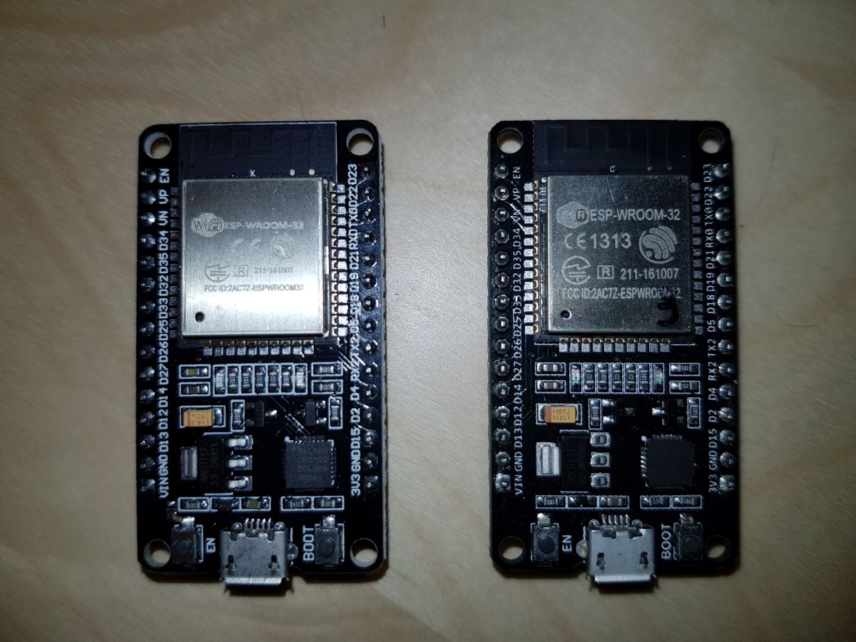
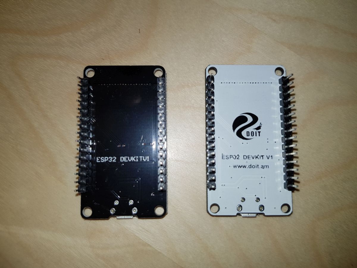
The ESP32 arrived, WiFi and BLE connectivity, a bunch of IO pins, a lot of different pin working modes… and for someone with limited knowledge of electronic theory… a marvelous tiny thing.

Lately, I am having much more spare time that I used to have, so I decided to start doing things I always wanted to do but I never had the time to. I don’t like using my cellular for all purpose. I like WakeUp alarm clocks, but not the ones they sell. My last WakeUp alarm was a Sony, very nice, spectacular design but “who the hell designs an alarm clock supposed to be stopped while you are sleeping by pressing a tiny switch in the middle of a lot of more tiny switches? Yes, Sony” And what if I design my own Alarm Clock with that ESP32 Developer board I have? And that’s what I did.

The requirements:

  1. Time visible in the dark, but not like a red UFO. Light intensity has to accommodate to room light.
  2. No need for time adjustment. No need to change the hour every spring or autumn.
  3. Minimal use of buttons, tiny buttons, micro switches… :S
  4. If there’s enough room on the screen… some other indicators like temperature and relative humidity (these are enough important in the dry & hot Madrid nights)
  5. If possible, some communication capabilities: remote configuration, remote alarm stopping, …
  6. Easy to wire components between

The prototype:

I needed a box to fit all the components in. Perfect reason to buy my first 3D printer, and that’s what I did.

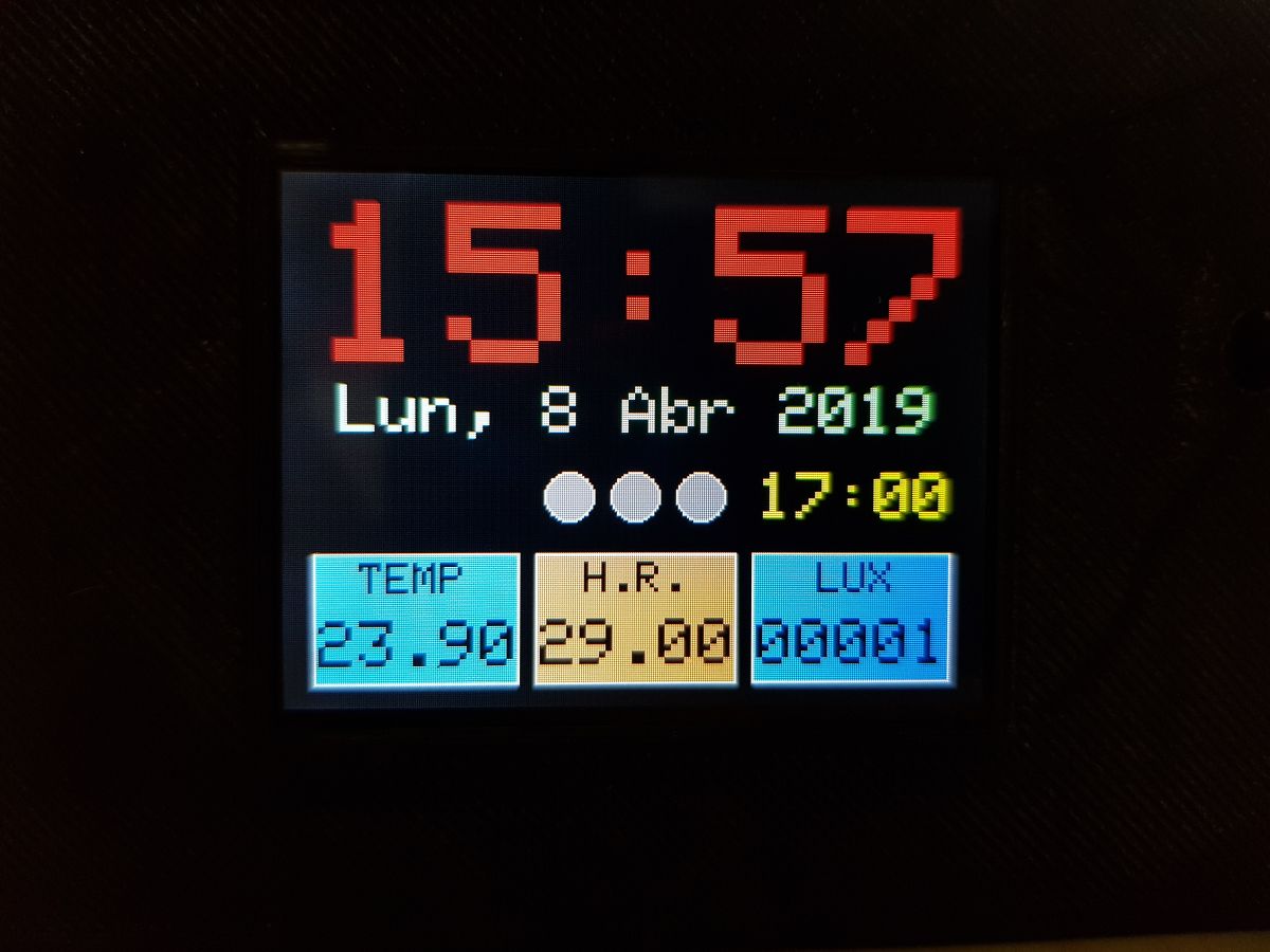
This is the screen design today… it’s evolving and probably will not be the same in a couple of days.

Claudio WakeUp Alarm Screen

The box is 11cm x 65mm x 65mm and though is a bit bigger than I expected it to be I think of it as a prototype and time will bring smaller designs.

Claudio Wake Up alarma box
Claudio Box

This has been only the introduction. Check out the rest of the posts to know more about the design, the code and the possibilities of ‘the creature’.