Xiaomi Mi Smart is a digital scale with BLE interface. This allows it to broadcast your weight to any device like your smart phone and incorporate the measurements to an application like Samsung Health.
Xiaomi Mi Smart Scale
Two years ago I was trying to read BLE messages from an ESP32, but Arduino BLE libraries didn’t work very well at that moment and all I got were some headaches. I wasn’t even able to match the Weight Measurement remote characteristic, so once the ESP32 connected to the scale it wasn’t able to implement the callback functions.
Today I’ve tried again, and I made it work!!!
Calculate the UUIDs
I have used the BLE_Client example (under ESP32 dev board samples). In order to connect and read values from any device you need two unique identifiers (16 bit UUID alias):
where the Bluetooth_Base_UUID is 1000800000805F9B34FB (00000000-0000-1000-8000-00805F9B34FB)
In our case we will be using the string version of the 128bit uuid and that means all we have to do to calculate the long uuid for the service and the characteristic is concatenating the uuids (aliases and Bluetooth Base one) in the following way:
Service UUID: 0000181D-0000-1000-8000-00805F9B34FB
Bring your Xiaomi scale next to your ESP32 MCU and load the next sketch using Arduino IDE:
/**
 * An ESP32 BLE client to find Xiaomi Mi Smart weight scale
 * Author Pangodream
 * Date 2020.05.31
 */

#include "BLEDevice.h"
//Base UUIDs
//Weight Scale service
static BLEUUID srvUUID("0000181d-0000-1000-8000-00805f9b34fb");

/**
 * Callback class for each advertised device during scan
 */
class deviceCB: public BLEAdvertisedDeviceCallbacks {
 //Called on each advertised device
  void onResult(BLEAdvertisedDevice advertisedDevice) {
    // We have found a device, let us now see if it contains the service we are looking for.
    if (advertisedDevice.haveServiceUUID() && advertisedDevice.isAdvertisingService(srvUUID)) {
      if(advertisedDevice.getName() != "MI_SCALE"){
        Serial.print("Weight scale (no MI_SCALE) device found with address ");
        Serial.print(advertisedDevice.getAddress().toString().c_str());
        Serial.print(" and name ");
        Serial.println(advertisedDevice.getName().c_str());
      } else {
        Serial.print("Xiaomi Mi Smart weight scale found with address ");
        Serial.println(advertisedDevice.getAddress().toString().c_str());
        BLEDevice::getScan()->stop();
        Serial.println("End of scan");
      }
    } else {
      Serial.print("Non weight scale device found with address ");
      Serial.println(advertisedDevice.getAddress().toString().c_str());
    }
  }
};

void setup() {
  Serial.begin(115200);
  Serial.println("Devices scan");
  BLEDevice::init("");
  BLEScan* pBLEScan = BLEDevice::getScan();
  pBLEScan->setAdvertisedDeviceCallbacks(new deviceCB());
  pBLEScan->setInterval(1349);
  pBLEScan->setWindow(449);
  //Set active scan
  pBLEScan->setActiveScan(true);
  //Scan during 5 seconds
  pBLEScan->start(5, false);
}

void loop() {

  delay(1000);
}
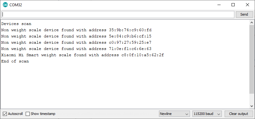
The sketch starts an active scan to find all the BLE servers (devices) that are advertising themselves at that moment.
The scan results are shown at the Serial Monitor (115200 bauds) and if a Xiaomi Mi Smart scale is found (and its name is MI_SCALE) something like the next should appear in your monitor:
If your weight scale was present in the scan and you can read the message “Xiaomi Mi Smart weight scale found with address xx:xx:xx:xx:xx:xx” then you can continue with our next goal, which is to retrieve data from weight measurement.
Retrieving data
When the ESP32 is scanning for devices, it only reads the service beacons sent by each BLE server to advertise itself, but when we use the scale and it broadcasts the calculated weight, it doesn’t send the same type of message (it is not a service message, but a characteristic one).
Note that we haven’t used yet the characteristic UUID we calculated before and we’ve only used the service one.
Let’s load a new sketch into the ESP32 MCU to retrieve some data from the characteristic:
/**
 * An ESP32 BLE client to retrieve data from the Weight Measurement characteristic
 * of a Xiaomi Mi Smart weight scale
 * Author Pangodream
 * Date 2020.05.31
 */

#include "BLEDevice.h"
//Base UUIDs
//Weight Scale service
static BLEUUID srvUUID("0000181d-0000-1000-8000-00805f9b34fb");
//Weight Measurement characteristic
static BLEUUID chrUUID("00002a9d-0000-1000-8000-00805f9b34fb");

static BLEAdvertisedDevice* scale;
static BLERemoteCharacteristic* remoteChr;
static boolean doConnect = false;
static boolean connected = false;
static int year = 0;

/**
 * Callback function for characteristic notify / indication
 */
static void chrCB(BLERemoteCharacteristic* remoteChr, uint8_t* pData, size_t length, bool isNotify) {
    //Console debugging
    Serial.print("Received data. Length = ");
    Serial.print(length);
    Serial.print(". - Data bytes: ");
    for(int i =0; i< length; i++){
      Serial.print(pData[i]);
      Serial.print("  ");
    }
    Serial.println(" ");
    //End of console debugging

    //Parsing the received data and calculate weight
    boolean temporary = true;
    int rcvdYear = pData[3];
    //If we received a year for the first time, store it in the year variable
    //The first year we receive indicates a temporary measurement
    if(year == 0){
      year = rcvdYear;
    }else{
      //If year has been previously defined and the year we have received is
      //greater than it, then the measurement is not temporary, is the final one
      if(rcvdYear > year){
        temporary = false;
      }
    }
    double weight = 0;
    weight = (pData[1] + pData[2] * 256) * 0.005;

    Serial.print("Weight: ");
    Serial.print(weight);
    Serial.print(" Kg - ");
    if(temporary){
      Serial.println(" (Provisional)");
    }else{
      Serial.println(" (Definitive)");
    }
}

/**
 * Callback class for each advertised device during scan
 */
class deviceCB: public BLEAdvertisedDeviceCallbacks {
 //Called on each advertised device
  void onResult(BLEAdvertisedDevice advertisedDevice) {
    // We have found a device, let us now see if it contains the service we are looking for.
    if (advertisedDevice.haveServiceUUID() && advertisedDevice.isAdvertisingService(srvUUID)) {
      if(advertisedDevice.getName() != "MI_SCALE"){
        Serial.print(".");
      } else {
        Serial.println("  Found!");
        BLEDevice::getScan()->stop();
        Serial.println("Stopping scan and connecting to scale");
        scale = new BLEAdvertisedDevice(advertisedDevice);
        doConnect = true;
      }
    } else {
      Serial.print(".");
    }
  }
};
/**
 * Callback class for device events
 */
class ClientCB : public BLEClientCallbacks {
  void onConnect(BLEClient* pclient) {

  }

  void onDisconnect(BLEClient* pclient) {
    Serial.println("Disconnected. Reconnecting...");
    connected = false;
  }
};

bool connectToScale() {
    Serial.println("Stablishing communications with scale:");
    BLEClient*  pClient  = BLEDevice::createClient();
    Serial.println("    BLE client created");

    pClient->setClientCallbacks(new ClientCB());

    // Connect to the remove BLE Server.
    pClient->connect(scale);
    Serial.println("    Connected to scale");

    // Obtain a reference to the service we are after in the remote BLE server.
    BLERemoteService* pRemoteService = pClient->getService(srvUUID);
    if (pRemoteService == nullptr) {
      Serial.println("    Error: Failed to find service");
      pClient->disconnect();
      return false;
    }
    Serial.println("    Service found");

    remoteChr = pRemoteService->getCharacteristic(chrUUID);
    if (remoteChr == nullptr) {
      Serial.print("    Failed to find characteristic");
      pClient->disconnect();
      return false;
    }
    Serial.println("    Characteristic found");
    Serial.println("    Setting callback for notify / indicate");
    remoteChr->registerForNotify(chrCB);
    return true;
}

void setup() {
  Serial.begin(115200);
  Serial.println("Searching for MI_SCALE device");
  BLEDevice::init("");
  BLEScan* pBLEScan = BLEDevice::getScan();
  pBLEScan->setAdvertisedDeviceCallbacks(new deviceCB());
  pBLEScan->setInterval(1349);
  pBLEScan->setWindow(449);
  //Set active scan
  pBLEScan->setActiveScan(true);
  //Scan during 5 seconds
  pBLEScan->start(5, false);
}

void loop() {
  if(doConnect && !connected){
    connected = connectToScale();
  }
  delay(1000);
}
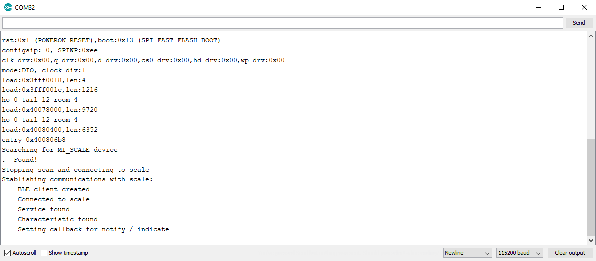
Reboot the MCU and take a look to the serial monitor. If everything goes right, something similar to this should be shown:
The sketch performs these tasks:
Scan devices to find the Xiomi scale
Connects to the scale
Search for the Weight Scale service
Instantiates the service
Search for the remote characteristic
Instantiates the remote characteristic
Sets the callBack function for the characteristic
In this way, when the scale begins to measure weight, our callback function will be invoked receiving the data.
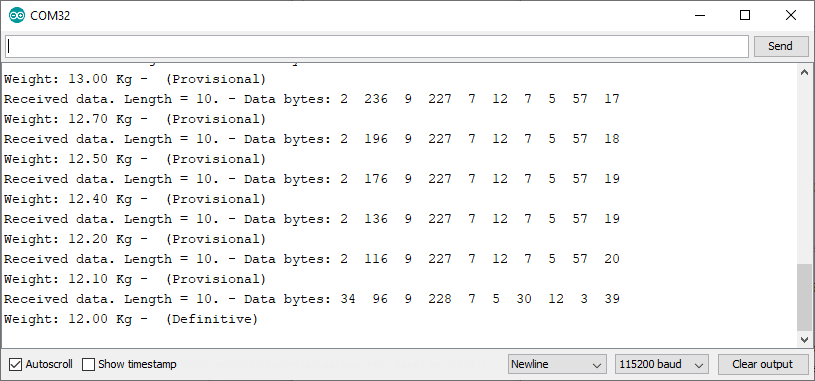
At this point, the ESP32 is waiting to receive something in the callBack function. Put some weight over the scale and you should see the provisional and definitive measurements at the serial monitor.
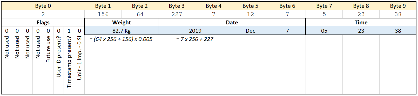
The callback function always receive 10 bytes of information. These bytes can be parsed to get the weight and timestamp values in the following way:
Parsing the XIOMI Scale BLE data
The way we can differentiate between the provisional and the definitive measurements is looking at the year in the timestamp. While measurements are provisional, the scale sends a fake year and not the current one. So, all we hve to do is taking note of the value for the year in the first data packet we receive and then compare to the rest of the years we receive.
When the received year is greater than the first year we received that is the definitive measurement and we can get the calculated weight.
Why BLE_client sketch doesn’t work
If yoy try the sketch located at File / Examples / ESP32 BLE Arduino / BLE Client it won’t work and will not receive any chararteristic message even when you change the UUIDs.
To set the callback function for the remote characteristic, first it checks the characteristic can be notifiable (method canNotify()) and our characteristic is not.
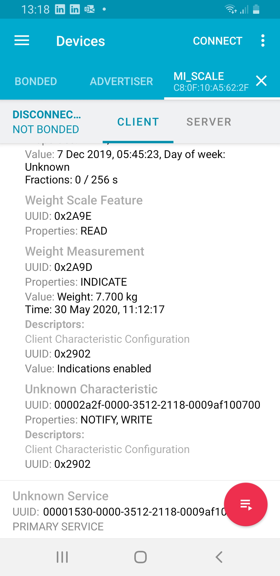
If you study the BLE connection using any app for that purpose (I use nRF Connect from Nordic Semiconductor) you will notice that the characteristic we are using is not notifiable but ‘indicate’ type:
So, if you comment out the condition to avoid checking if the characteristic is notifiable or not, and set the callback function anyway, you will received calls in the callback function with the parameter isNotify set to false.
First of all, please read the post title. This doesn’t work on an ESP32 MCU.
I only made it work on an ESP8266 MCU.
This afternoon I received a couple of MAX30100 sensors that I ordered some days before (44 days, China, COVID19, …)
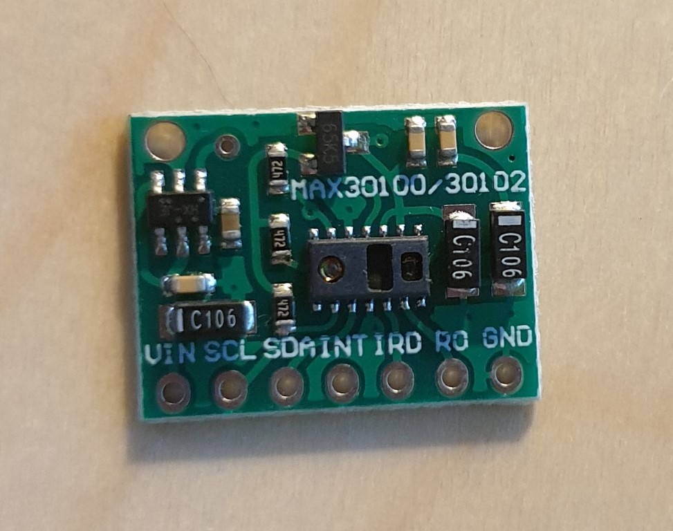
MAX30100 Sensor Board
The board is quite easy to connect: it has an I2C interface and you even don’t need the INT pin, so all you have to do is wiring the SDA and SCL pins.
I used D22 and D21 pins in my ESP32 MCU, as they are also used for I2C_SDA and I2C_SCL interfacing (checkout pinout diagram here)
Summarizing, the pins you need to connect are:
ESP32 GND to SENSOR GND
ESP32 3.3 to SENSOR VIN
ESP32 D22 to SENSOR SDA
ESP32 D21 to SENSOR SCL
Once you have all the pins connected it’s software time.
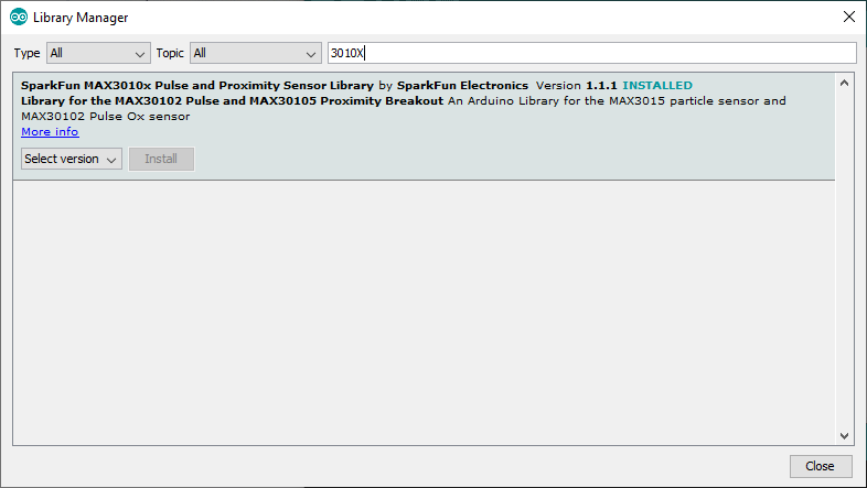
In Arduino IDE, select Manage Libraries and install the Sparkfun MAX3010X Library
After that, you are ready to open any of the examples provided with the library and test the module.
Probably you will notice that doesn’t work correctly. It seems to initialize the module correctly and even it starts to make some measurements. You even would think that is working for a few seconds, but it isn’t.
The behaviour, at least in my case, is the next:
The module initialize with a SUCESS status
It lights on the red led
You put your finger over the sensor
It starts measuring, but after a second the red led goes off
It seems to measure intermittently
If this is your case, don’t waste your time. I was searching for troubleshootings and all I found was replacing the inbuilt 4K7 resistors or bypassing the voltage limiter in the sensor board. Don’t do it, it is not a problem of pull-up resistors.
I decided then to try with an ESP8266 MCU and this is the result:
The sensor board works fine, so probably it is a problem of compatibility between the library and ESP32.
The sensor measures heart rate and SpO2. I only used the heartBeat event to light the led to show that it works.
Some of the ESP32 development boards provide a 3.7 Ion-Li battery charger what is an advantage when we want to get a device with the minimum number of components.
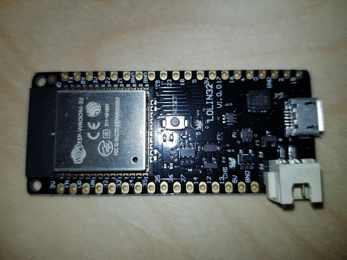
One of these boards is Wemos Lolin 32 (with battery charger) which costs about 7$ in eBay.
Wemos Lolin 32
When a battery is plugged in and the board is connected to a power source via the USB connector, the battery starts being charged.
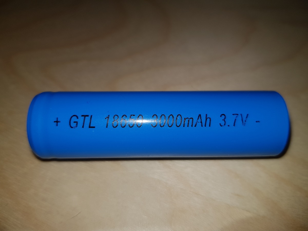
As the ESP32 board counts with several ADC pins, we can use one of them to check the voltage in between the two battery terminals. The only issue with this is that ADC pins expect voltages between 0 and 3.3 volts and our Ion-Li battery voltage range may reach 4.2 volts.
18650 Ion-Li Battery
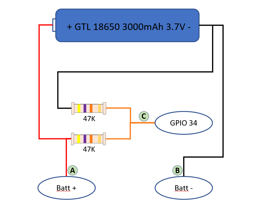
The solution to that is connecting a voltage divider to the battery, so we can divide the volts by 2 and the maximum value will be about 2.1 volts.
Voltage Divider SchemaVoltage Divider
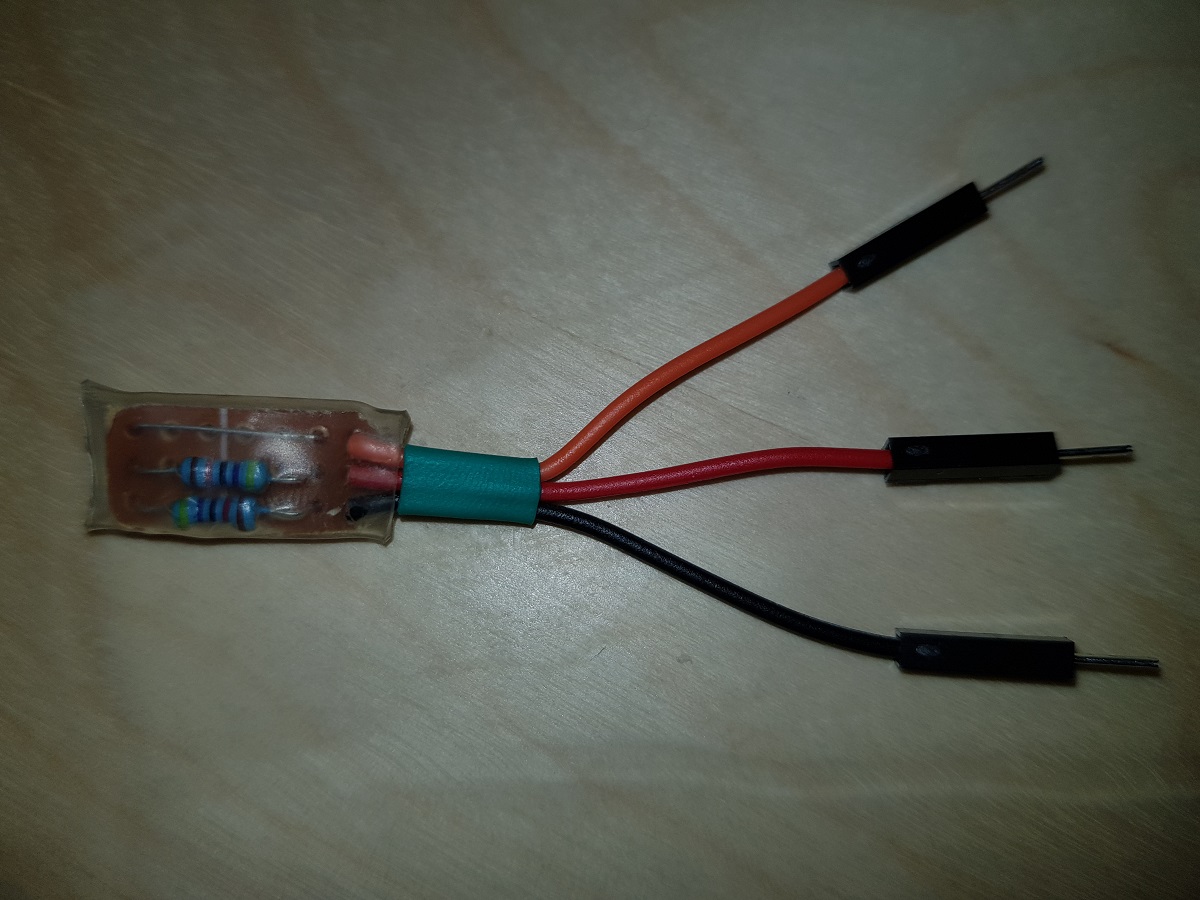
Our voltage divider is built of two 47KΩ resistors. The total impedance between positive and negative terminals will be 94KΩ and that means a current of less than 5 50μA (microamperes, not milliamperes).(Thanks Jonathan)
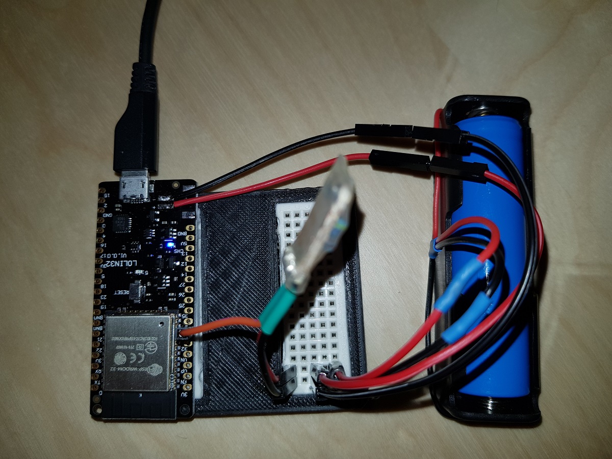
Voltage Divider mounted on Lolin 32
With this, we can measure the voltage applied in GPIO34 (or any other ADC pins of our ESP32) and then, based on a conversion table, calculate the charge level of the battery.
First, we will get the value of ADC pin. This value may vary from 0 to 4096 depending on the voltage applied to it from 0V to 3.3V. So we can establish a constant to calculate the voltage applied to the pin based on its value. This constant, theoretically, will be 3300 / 4096 = 0.8056.
As we are applying a voltage divider and the voltage applied to the pin is half the voltage of the battery, our constant should be 0.8056 x 2 = 1.6113.
This means, for each unit in ADC pin we have 1.6113 mVolts applied to it.
For instance, if we read the value of the ADC pin and get 2,543, then the voltage applied to the pin should be 2,453 x 1.6113 = 3,952V = 3.95V
ADC pins are not that precise, so the value of our constant should be adjusted to a level we consider it is valid for our components. In my case, after doing some testings I have concluded that the best value for the conversion factor is 1.7.
As I mentioned before, calculating the charge level is a direct translation from the voltage we obtained to a charge level by using a table.
All the code to make these calculations is contained in a library I have created for that purpose. You can find it in Github at Pangodream_18650CL.
All you have to do is downloading the .zip file and add it to Arduino IDE.
There is an example of using the library:
#include <Pangodream_18650_CL.h>

//#define ADC_PIN 34
//#define CONV_FACTOR 1.7
//#define READS 20

Pangodream_18650_CL BL;
/**
 * If you need to change default values you can use it as
 * Pangodream_18650_CL BL(ADC_PIN, CONV_FACTOR, READS);
 */

void setup() {
  Serial.begin(115200);
}

void loop() {
  Serial.print("Value from pin: ");
  Serial.println(analogRead(34));
  Serial.print("Average value from pin: ");
  Serial.println(BL.pinRead());
  Serial.print("Volts: ");
  Serial.println(BL.getBatteryVolts());
  Serial.print("Charge level: ");
  Serial.println(BL.getBatteryChargeLevel());
  Serial.println("");
  delay(1000);
}
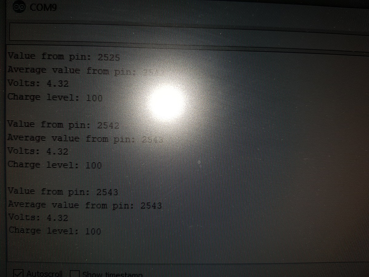
And if everything works, it should display something like this on your serial terminal:
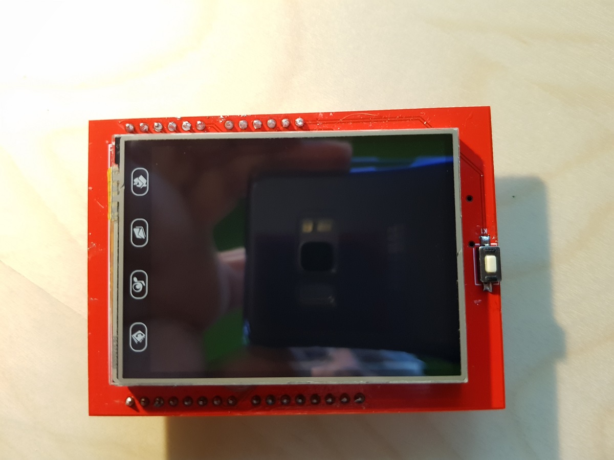
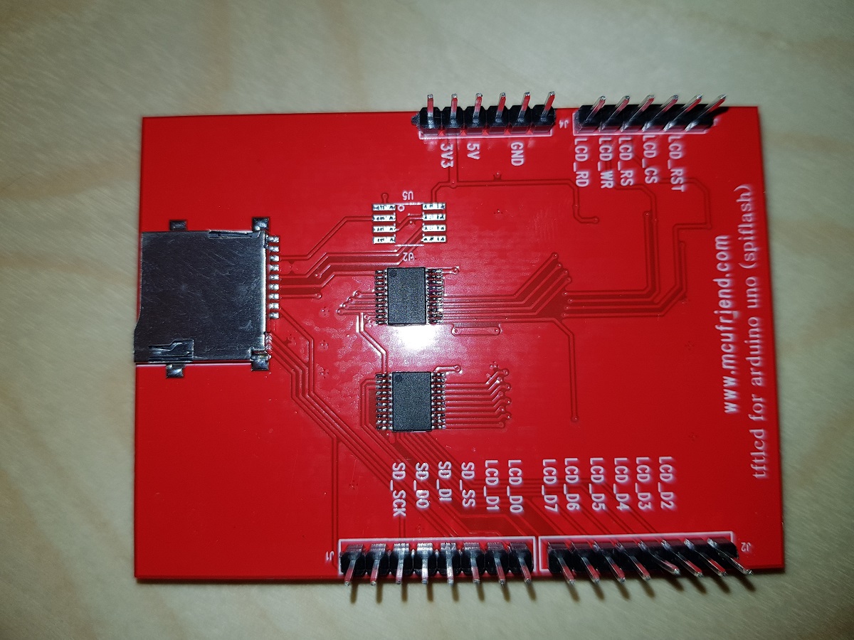
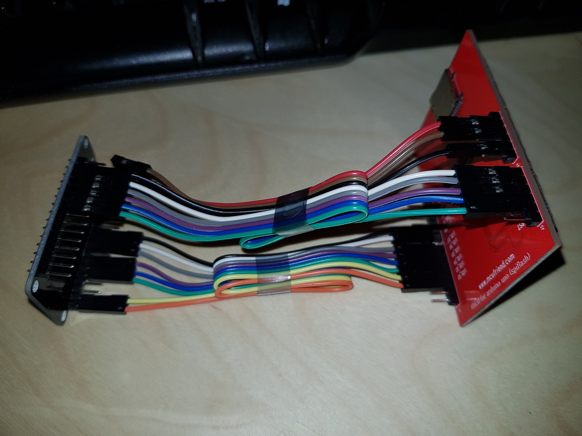
Today I’ve received two ILI9341 TFT screens that I ordered some weeks ago. These screens are in fact a shield designed for Arduino Uno but they work nicely when connected to other developer boards and the price is amazingly cheap: just US$4.
ILI9341 FrontILI9341 Back
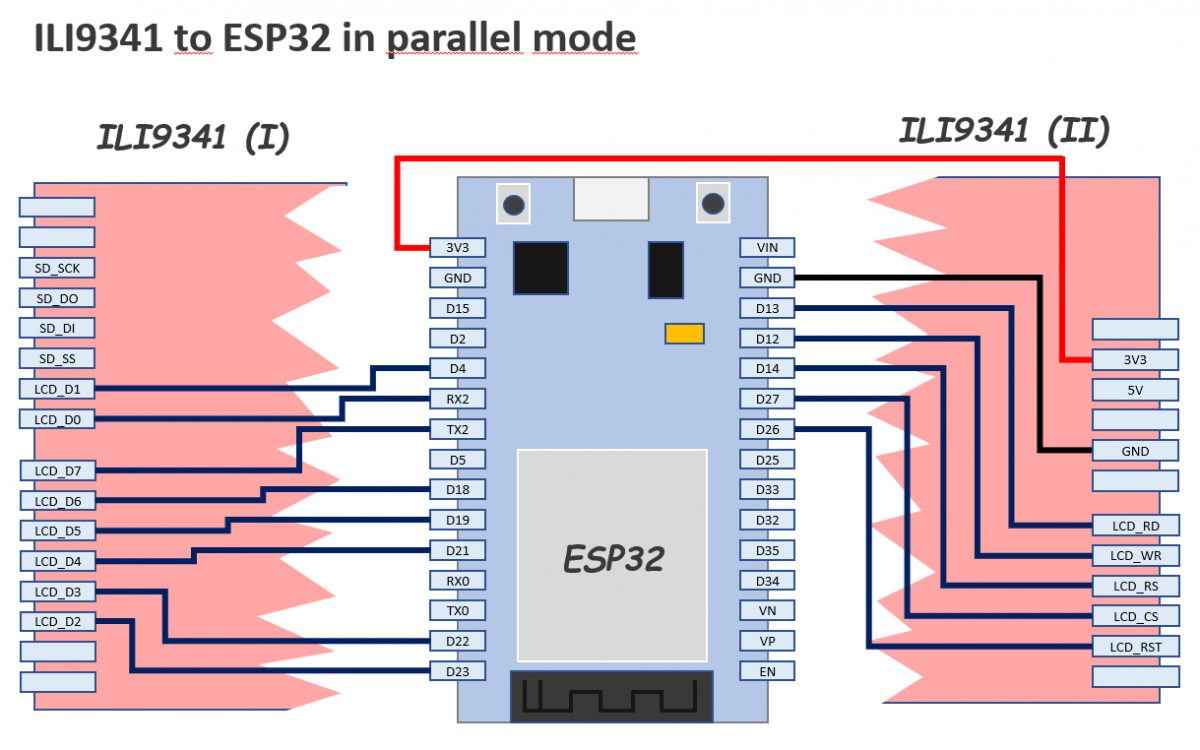
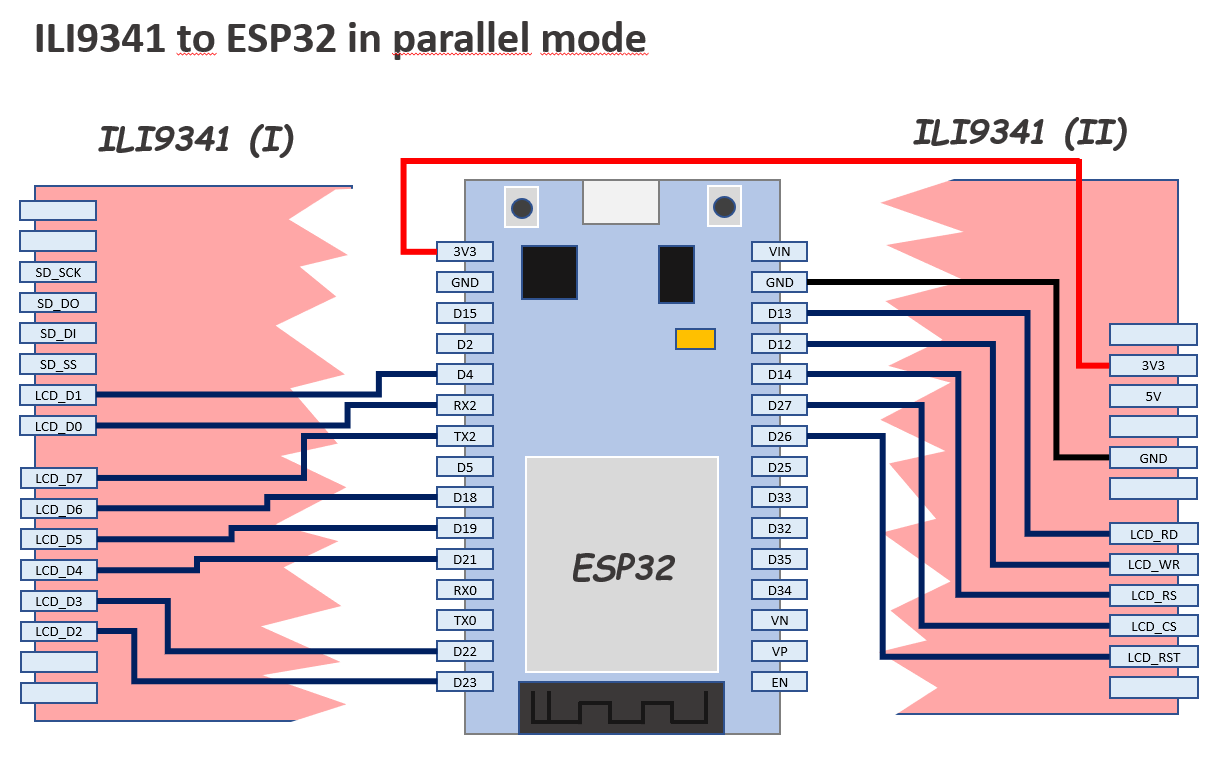
In this case, we will connect the screen to an ESP32 Dev Board.
The pins are configured in a slightly different way than other examples you could find in the web: I’ve tried to minimize mistakes because we will use 13 pins so I thought the best way would be to use as much as possible consecutive pins.
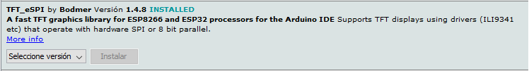
The library we will use is TFT_eSPI library by Bodmer and our only purpose by the moment will be executing an example demo script successfully.
During testing, you can connect TFT 3V3 pin directly to ESP32 3V3 pin, but do it only during a short period of time because the current drawn by the screen LEDs is 134mA and you will notice how the LEDs and the Development Board voltage limiter will become hot.
A 22Ω resistor (not 220) between the two 3V3 pins it’s enough to reduce the current to 23mA and though the screen is not the brightest one in the world I think it is enough for testing purposes.
Once you have finished the connection of the pins as described in the diagram above, you can install the TFT_eSPI library if you don’t have it already installed.
Open Arduino IDE, go to Library Manager and in the search box type TFT_eSPI. In the results list, look for the next and install it.
TFT_eSPI Bodmer Library for Arduino
Now you have the library installed you have to configure the IO pins where we have connected our screen. Other libraries use the definition of constants at the top of each sketch to do this, but TFT_eSPI uses a common file to define the configuration.
Find in your Arduino installation the file called User_Setup.h
It should be located in a path equivalent to this:
[Arduino Folder]/libraries/TFT_eSPI/User_Setup.h
Now, copy the file for backup purposes and edit the original to place inside it this following content (replacing all the previous content):
// See SetupX_Template.h for all options available

#define ESP32_PARALLEL


#define ILI9341_DRIVER


// ESP32 pins used for the parallel interface TFT
#define TFT_CS   27  // Chip select control pin
#define TFT_DC   14  // Data Command control pin - must use a pin in the range 0-31
#define TFT_RST  26  // Reset pin

#define TFT_WR   12  // Write strobe control pin - must use a pin in the range 0-31
#define TFT_RD   13

#define TFT_D0   16  // Must use pins in the range 0-31 for the data bus
#define TFT_D1   4  // so a single register write sets/clears all bits
#define TFT_D2   23
#define TFT_D3   22
#define TFT_D4   21
#define TFT_D5   19
#define TFT_D6   18
#define TFT_D7   17


#define LOAD_GLCD   // Font 1. Original Adafruit 8 pixel font needs ~1820 bytes in FLASH
#define LOAD_FONT2  // Font 2. Small 16 pixel high font, needs ~3534 bytes in FLASH, 96 characters
#define LOAD_FONT4  // Font 4. Medium 26 pixel high font, needs ~5848 bytes in FLASH, 96 characters
#define LOAD_FONT6  // Font 6. Large 48 pixel font, needs ~2666 bytes in FLASH, only characters 1234567890:-.apm
#define LOAD_FONT7  // Font 7. 7 segment 48 pixel font, needs ~2438 bytes in FLASH, only characters 1234567890:.
#define LOAD_FONT8  // Font 8. Large 75 pixel font needs ~3256 bytes in FLASH, only characters 1234567890:-.
#define LOAD_GFXFF  // FreeFonts. Include access to the 48 Adafruit_GFX free fonts FF1 to FF48 and custom fonts

#define SMOOTH_FONT
Save the file and go back to Arduino IDE.
Open the example sketch UTFT_demo (it is under File / Examples / TFT_eSPI / 320 x 240 / UTFT_demo)
At this point, you can compile and upload the sketch to your ESP32. If everything went ok you should see some graphics, backgrounds and texts appearing in your TFT screen. Otherwise please review carefully the IO pins configuration (hard and soft).
If it works, probably you’ll see the results like in a mirror. To solve this, go to the sketch and edit the line that sets the screen orientation. This is done in the setup function.
void setup()
{
  randomSeed(analogRead(A0));
// Setup the LCD
  myGLCD.init();
  //myGLCD.setRotation(1); //Comment out this one and insert the one below
  myGLCD.setRotation(7);
}
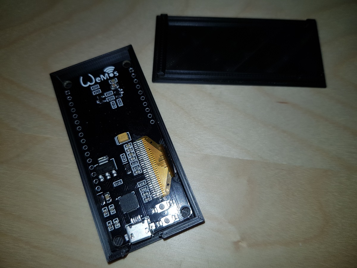
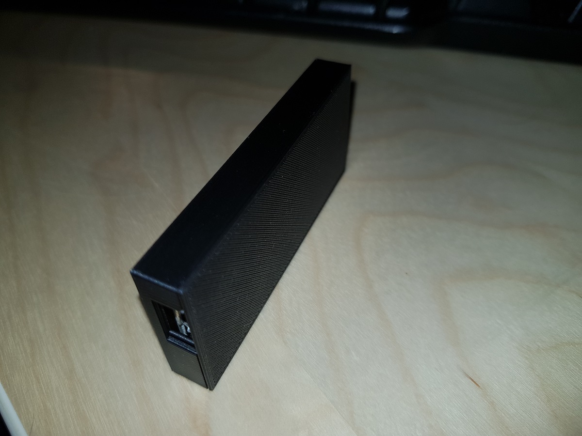
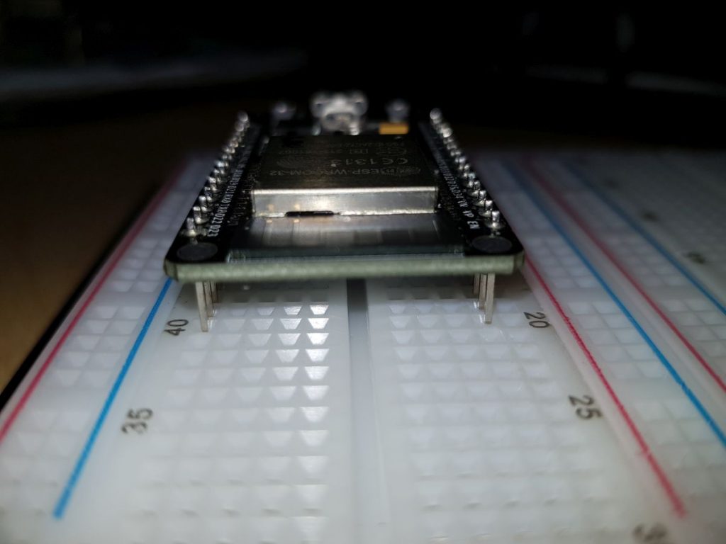
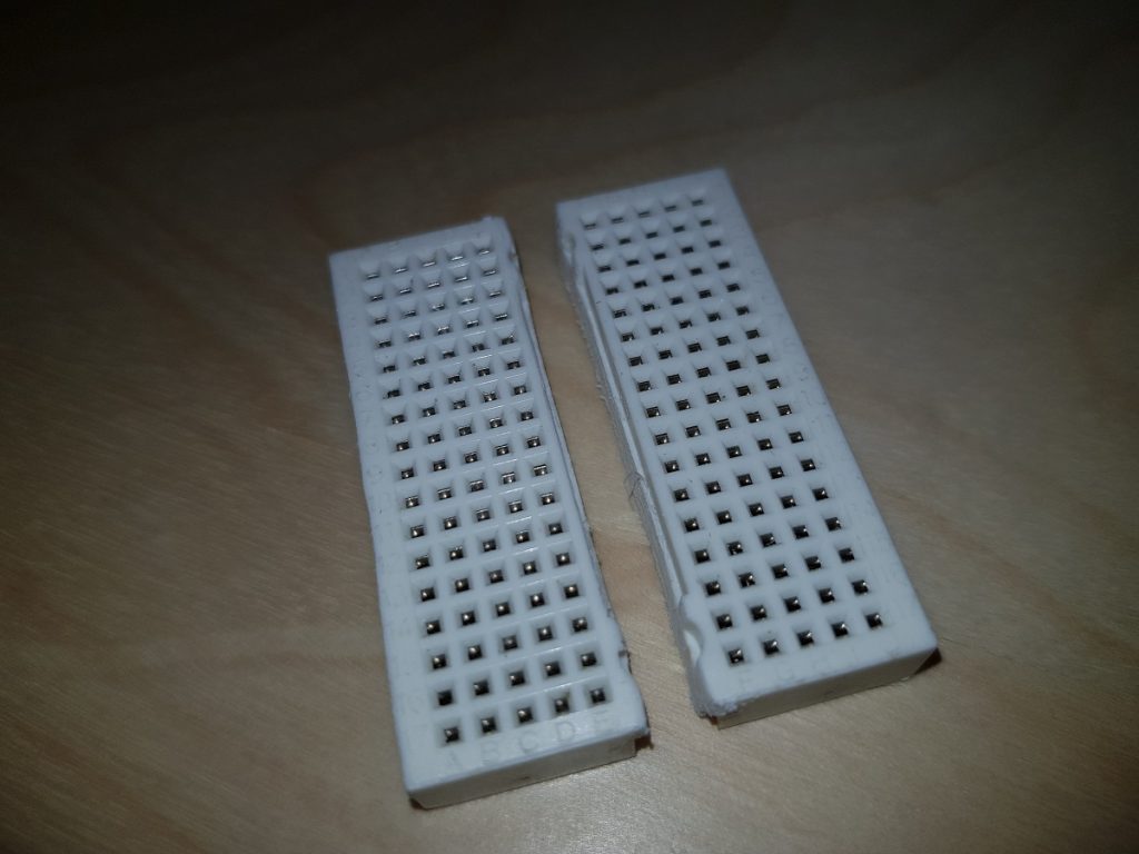
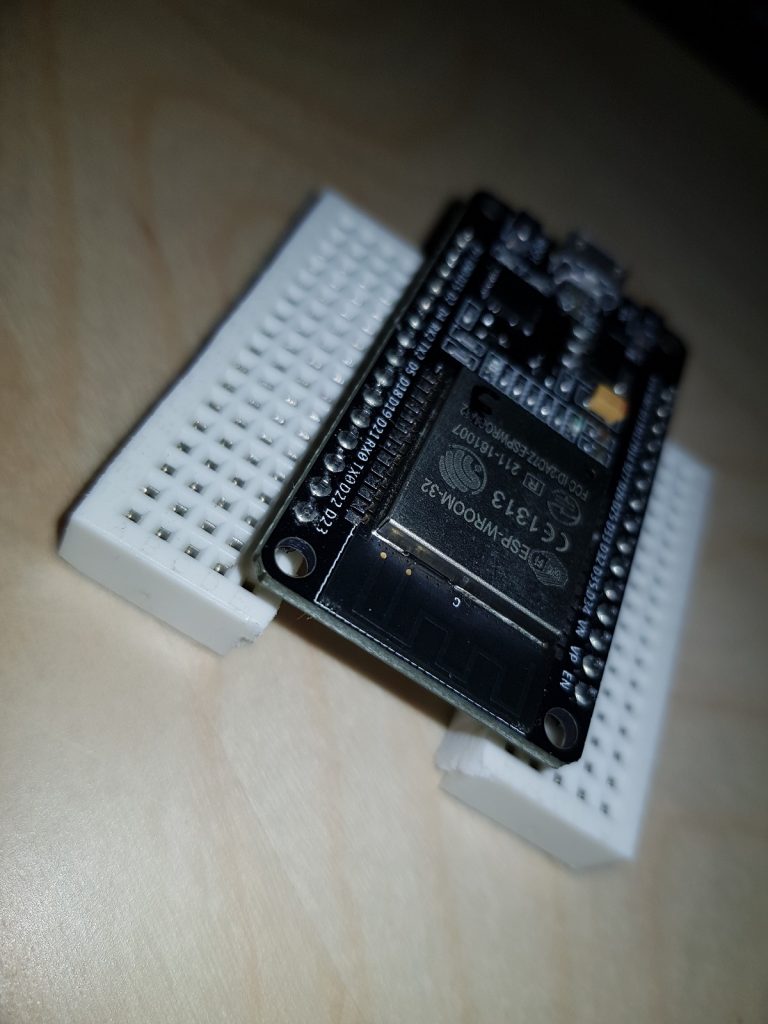
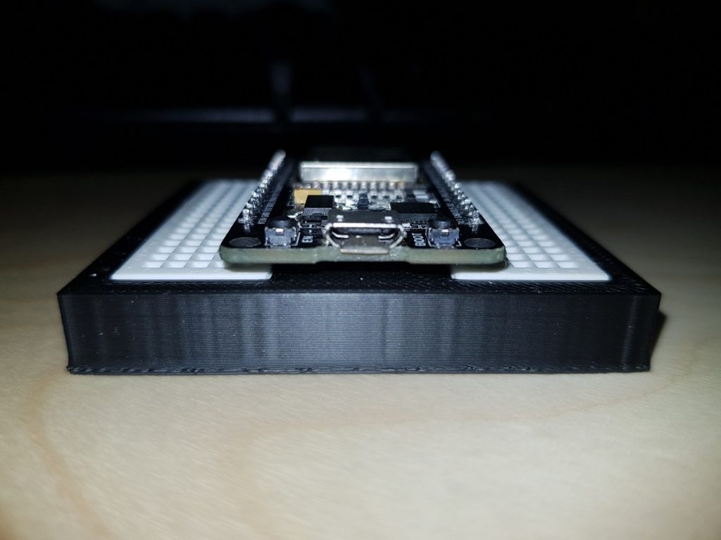
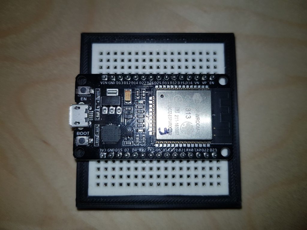
It is frustrating the first time you insert an ESP32 dev board into a breadboard and you notice there’s no room for wires.
ESP Dev Board on Breadboard
What I usually do is putting a breadboard aside another one, but I don’t like it very much.
Workaround for ESP Dev Board on two breadboards
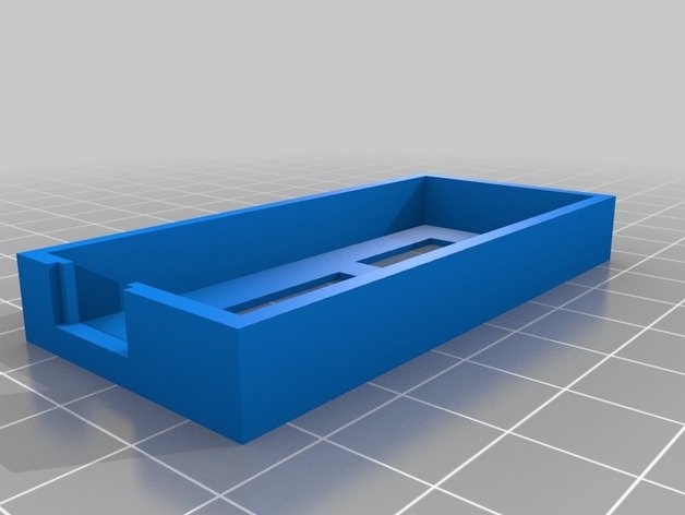
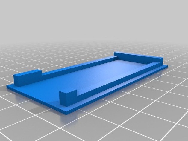
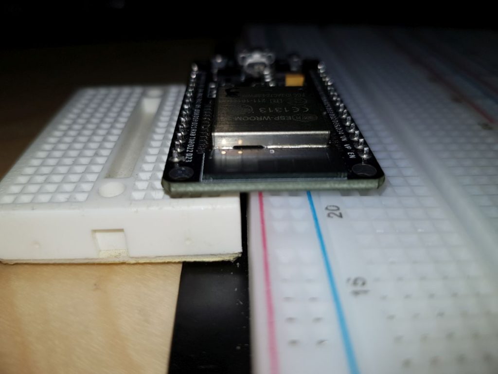
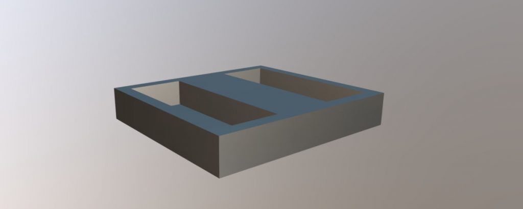
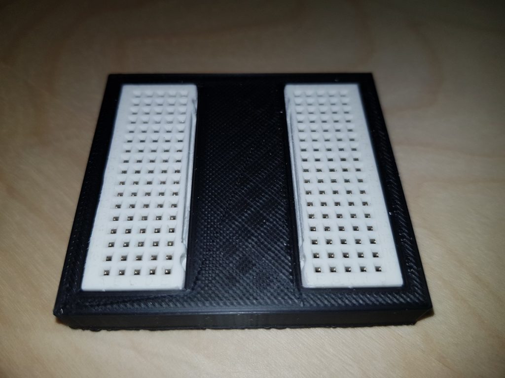
I decided then to split the small board into two pieces and insert them in a 3D printed base so that the dev board pins get into the first row of holes and the rest remain available.
Split breadboardESP32 Dev Board on the split breadboardBreadboard splitter
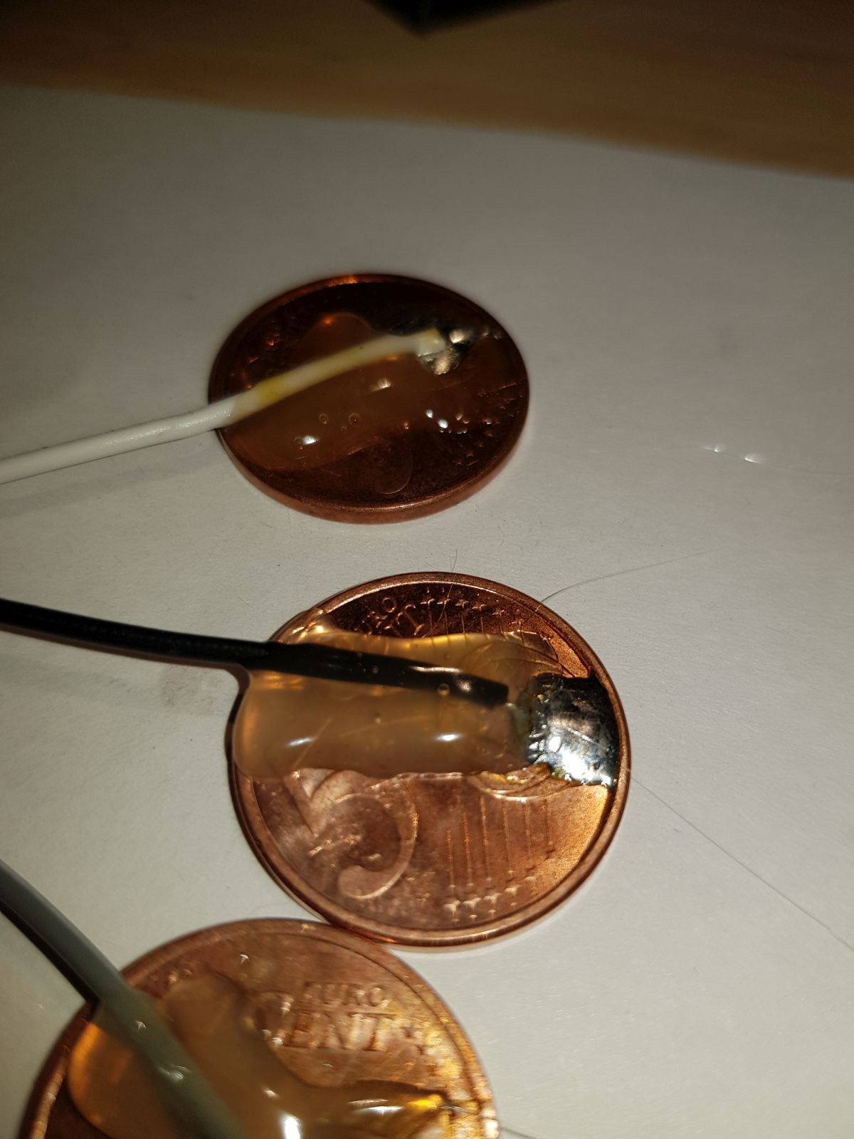
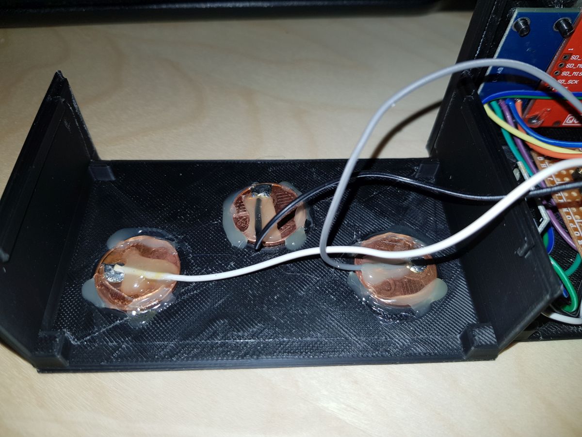
Claudio consists of just five (or six) components, the wiring between them and code. No resistors, capacitors, diodes… no discrete components apart from 3 five cents of € coins. 😉
List of components:
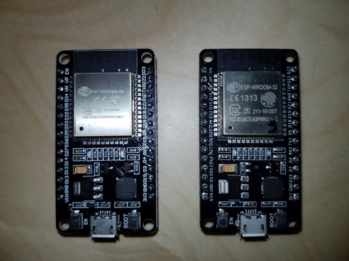
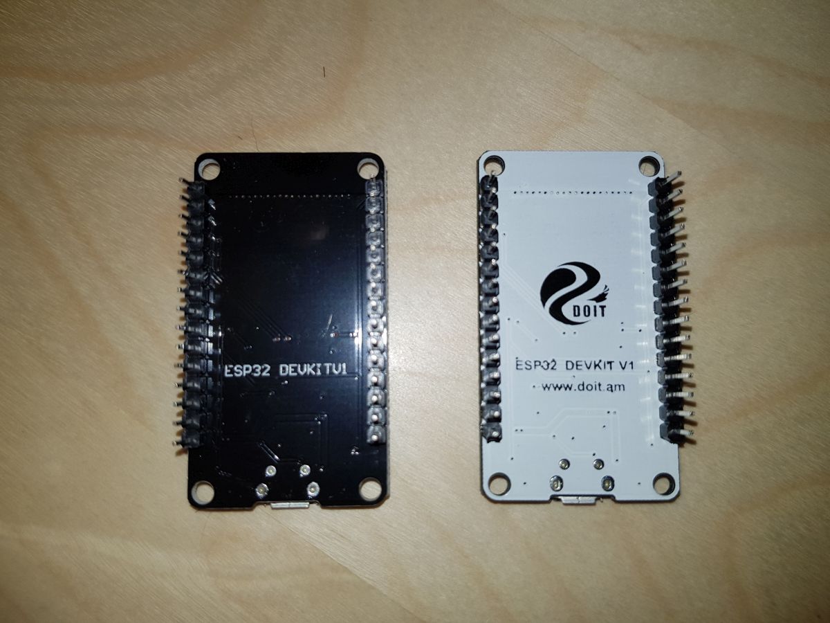
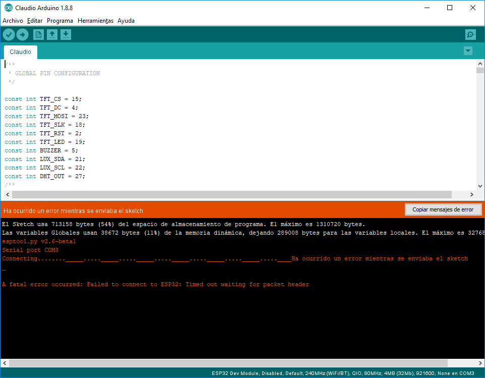
ESP32 Development Board: I’ve tested two different boards, and though they are very similar the results were not the same. ESP32 Development Boards Front ESP32 Development Boards Back Price: US $7 The first one was the one on the right side. It is a board I bought a year ago and it was working fine (for small tests) since then. When I first tried to put all the components together I noticed that ILI9341 TFT Display and WiFi connection were not good friends working at the same time. After 3 or 4 display operations (text, area fill, …) the screen went always blank and only when WiFi library was loaded. I tried multiple pin configurations, alternate libraries loading order. I tested voltage on each significant pin (D/C, CLOCK, MOSI) and no result. Finally, I decided to give a try one of the last boards I bought: the model on the left side. The result was successful. No blank screen. But, these boards have a bug design: they don’t allow uploading schemas directly from Arduino IDE (Error: Timed out waiting for packet header) and you have to ‘play’ with EN and BOOT buttons every time. Workaround: once Arduino IDE tries to upload the schema, press BOOT and without releasing it press also EN button, wait for a half second, release EN and when IDE stops waiting and starts the uploading you can release BOOT button.
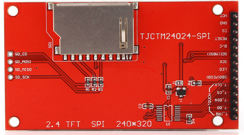
ILI9341TFT Screen – SPI Again, the component I had at home was about one year old. The only difference is that the one you can find now implements a set of pins to control a touch panel (though they say at the product description “non-touch”). Anyway, I think the one is being sold now is perfectly compatible with the previous model. What we need for this design is a model with an SPI pin configuration. Sellers usually refer to these as “driven with at least four IO” Price: US $7 ILI9341 SPI TFT DisplaySample ebay.com link to ILI9341
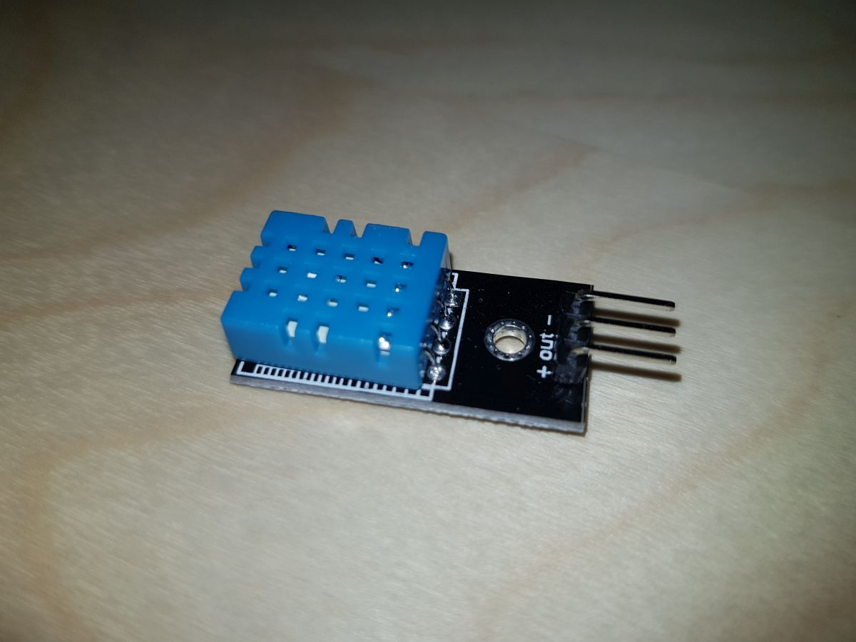
DHT-11 Temperature and Humidity Sensor This is a low-cost sensor very easy to use. Though it has four pins, only three of them have a function (the other one is not connected). Simply connect ground pin to GND, VCC pin to 3V3 and Data Out pin to any ESP32 IO pin. Depending on the range of temperature/humidity you need to measure, you should take a look also to DHT-22 sensor (which implements a wider range and more accuracy), but in my case, 0-50ºC/20-80%R.H. is quite enough. Price: US $1 DHT-110 Temperature and Relative Humidity sensor
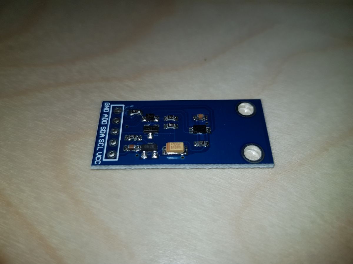
BH1750FVI Digital Light Intensity Sensor I think the best feature of this sensor is, apart from ease of use, the sensibility and stability. It measures ambient light and gives the result in Lux. It has 5 pins, but once again we can ignore one of them (ADD) by connecting it to GND. So, we only need two ESP32 IO pins to connect SDA and SCL sensor pins. GND and VCC pins go to GND and 3V3 ESP32 pins respectively. Price: US $1 BH1750FVI Ambient Light Sensorebay.com link to BH1750FVI search
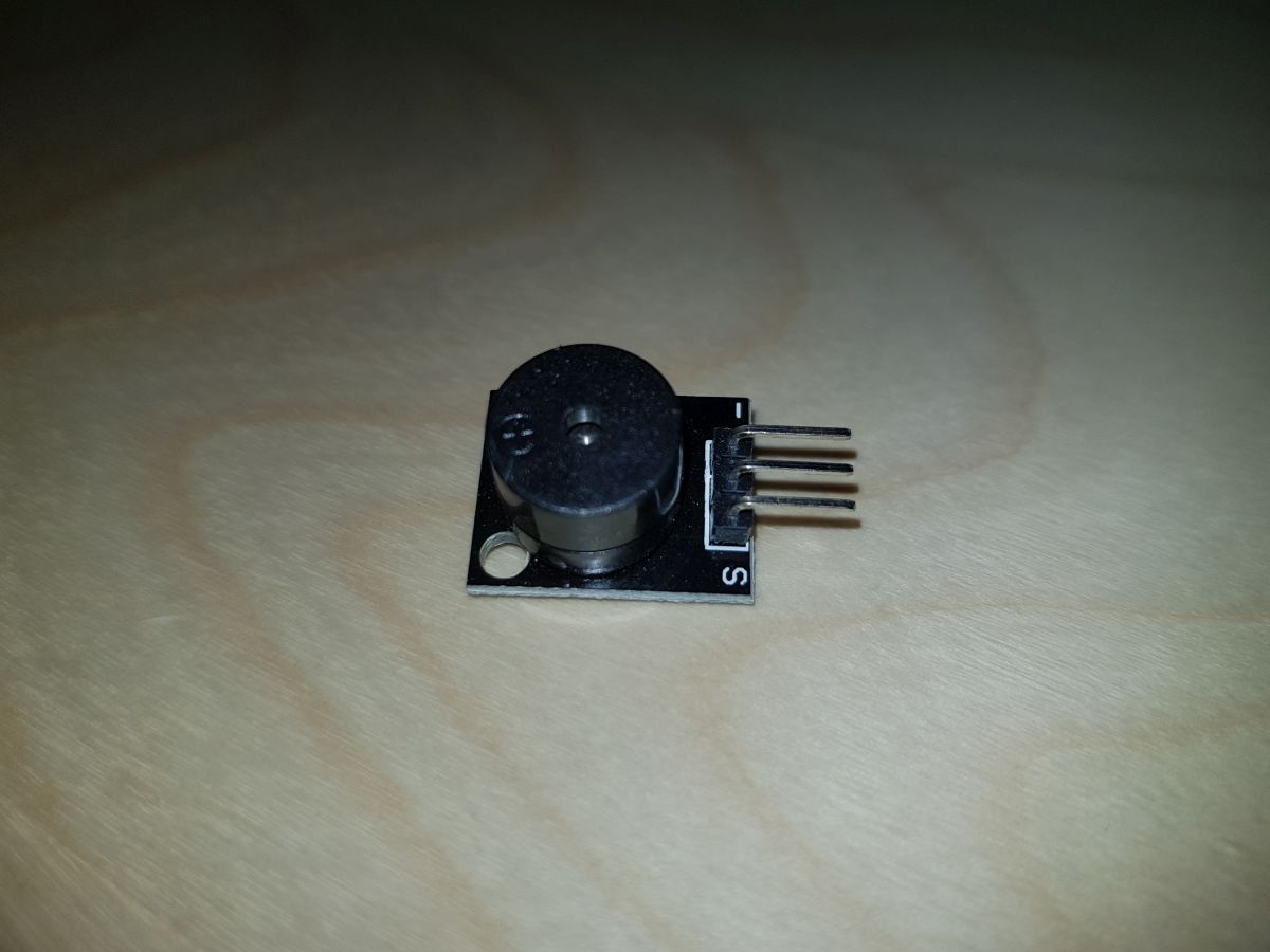
Passive Piezo Buzzer The most basic part of the system. Just two pins (the middle one can be ignored), one goes to GND and the other one to an ESP32 IO pin. Price: US $0.2 Passive Piezo Buzzer
After trying several options that I found on the web, I chose this one as the better to connect an ESP32 to an ILI9341 TFT display.
ESP32
ILI9341
3V3
VCC
GND
GND
D15
CS
D2
RESET
D4
D/C
D23
MOSI
D18
SCK
Not connected
MISO
3V3 (***or D19)
LED
The code:
/**
 * ILI9341 TFT libraries and resources
 */
const int TFT_CS = 15;
const int TFT_DC = 4;
const int TFT_MOSI = 23;
const int TFT_SLK = 18;
const int TFT_RST = 2;
const int TFT_LED = 19;

#include "SPI.h"
#include "Adafruit_GFX.h"
#include "Adafruit_ILI9341.h"
Adafruit_ILI9341 tft = Adafruit_ILI9341(TFT_CS, TFT_DC, TFT_MOSI, TFT_SLK, TFT_RST);

void setup() {
  tft.begin();
  tft.setRotation(3); //Landscape orientation
}
The reason for the two possibilities for the LED pin is the next:
If you connect LED pin directly to 3V3 you will get maximum brightness in your screen. LED pin controls the backlight of your TFT display.
In my case, I didn’t want to have max brightness but I wanted to control the intensity based on ambient light, so I decided to connect LED pin to any of the IO pins of the ESP32 (#19 in the showed example).
The code to control backlight intensity (once you have connected LED to pin D19) is as follows:
Inserting the code above allows you to set the backlight intensity at any point just invoking setBGLuminosity() function passing a value between 0 and 255.
This website uses cookies to improve your experience. We'll assume you're ok with this, but you can opt-out if you wish.AcceptReject
Privacy & Cookies Policy
Privacy Overview
This website uses cookies to improve your experience while you navigate through the website. Out of these, the cookies that are categorized as necessary are stored on your browser as they are essential for the working of basic functionalities of the website. We also use third-party cookies that help us analyze and understand how you use this website. These cookies will be stored in your browser only with your consent. You also have the option to opt-out of these cookies. But opting out of some of these cookies may affect your browsing experience.
Necessary cookies are absolutely essential for the website to function properly. This category only includes cookies that ensures basic functionalities and security features of the website. These cookies do not store any personal information.
Any cookies that may not be particularly necessary for the website to function and is used specifically to collect user personal data via analytics, ads, other embedded contents are termed as non-necessary cookies. It is mandatory to procure user consent prior to running these cookies on your website.