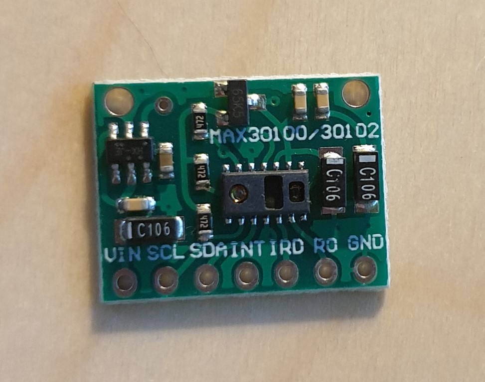
First of all, please read the post title. This doesn’t work on an ESP32 MCU.
I only made it work on an ESP8266 MCU.
This afternoon I received a couple of MAX30100 sensors that I ordered some days before (44 days, China, COVID19, …)

The board is quite easy to connect: it has an I2C interface and you even don’t need the INT pin, so all you have to do is wiring the SDA and SCL pins.
I used D22 and D21 pins in my ESP32 MCU, as they are also used for I2C_SDA and I2C_SCL interfacing (checkout pinout diagram here)
Summarizing, the pins you need to connect are:
ESP32 GND to SENSOR GND
ESP32 3.3 to SENSOR VIN
ESP32 D22 to SENSOR SDA
ESP32 D21 to SENSOR SCL
Once you have all the pins connected it’s software time.
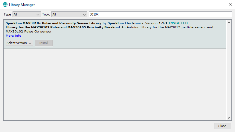
In Arduino IDE, select Manage Libraries and install the Sparkfun MAX3010X Library
After that, you are ready to open any of the examples provided with the library and test the module.
Probably you will notice that doesn’t work correctly. It seems to initialize the module correctly and even it starts to make some measurements. You even would think that is working for a few seconds, but it isn’t.
The behaviour, at least in my case, is the next:
- The module initialize with a SUCESS status
- It lights on the red led
- You put your finger over the sensor
- It starts measuring, but after a second the red led goes off
- It seems to measure intermittently
If this is your case, don’t waste your time. I was searching for troubleshootings and all I found was replacing the inbuilt 4K7 resistors or bypassing the voltage limiter in the sensor board. Don’t do it, it is not a problem of pull-up resistors.
I decided then to try with an ESP8266 MCU and this is the result:
The sensor board works fine, so probably it is a problem of compatibility between the library and ESP32.
The sensor measures heart rate and SpO2. I only used the heartBeat event to light the led to show that it works.


I have a ESP8266 NODE MCU and MAX30100/MAX30102 module. I am unable to make the connections.
Will you please send me the circuit diagram for ESP8266 NODE MCU and MAX30100/MAX30102 and the suggest the library to be used in ARDUINO IDE @aditya.rahul81@gmail.com soon.
Thanks for commenting Aditya.
I think you have enough information in the post to wire both circuits. Sorry, but I cannot send you a customized diagram (I don’t know the board you are working with…)
Regards
Did you bring any change in the max30100/max30102 module or else you simply made the connection between the module and esp8266 and it started working?
I made no change in the module. As I tell it was impossible to make it work with an ESP32 module, but when I tried with ESP8266 it worked with no issue.
If I were in your shoes, I would try the pull-up resistors trick that has worked for other people (though it was not the solution for the ESP32 in my case)
Good luck!
I have a ESP8266 NODE MCU and MAX30100/MAX30102 module. I am unable to make the connections.
Will you please send me the circuit diagram for ESP8266 NODE MCU and MAX30100/MAX30102 and the suggest the library to be used in ARDUINO IDE
Saidibachir172@gmail.com
I used the same sensor MAX30100 and connected it with Arduino UNO, but it keep giving me some garbled code in the serial monitor.Can u also show the code you used?
The code I used is the sample for Mini_D1 board.
/*

Arduino-MAX30100 oximetry / heart rate integrated sensor library

Copyright (C) 2016  OXullo Intersecans
This program is free software: you can redistribute it and/or modify
it under the terms of the GNU General Public License as published by
the Free Software Foundation, either version 3 of the License, or
(at your option) any later version.
This program is distributed in the hope that it will be useful,
but WITHOUT ANY WARRANTY; without even the implied warranty of
MERCHANTABILITY or FITNESS FOR A PARTICULAR PURPOSE. See the
GNU General Public License for more details.
You should have received a copy of the GNU General Public License
along with this program. If not, see
*/
#include
#include "MAX30100_PulseOximeter.h"
#define REPORTING_PERIOD_MS 1000
// PulseOximeter is the higher level interface to the sensor
// it offers:
// * beat detection reporting
// * heart rate calculation
// * SpO2 (oxidation level) calculation
PulseOximeter pox;
uint32_t tsLastReport = 0;
// Callback (registered below) fired when a pulse is detected
void onBeatDetected()
{
Serial.println("Beat!");
digitalWrite(14, HIGH);
delay(150);
digitalWrite(14, LOW);
}
void setup()
{
Serial.begin(115200);
Serial.print("Initializing pulse oximeter..");
// Initialize the PulseOximeter instance
// Failures are generally due to an improper I2C wiring, missing power supply
// or wrong target chip
if (!pox.begin()) {
Serial.println("FAILED");
for(;;);
} else {
Serial.println("SUCCESS");
}
// The default current for the IR LED is 50mA and it could be changed
// by uncommenting the following line. Check MAX30100_Registers.h for all the
// available options.
// pox.setIRLedCurrent(MAX30100_LED_CURR_7_6MA);
pinMode(14, OUTPUT);
// Register a callback for the beat detection
pox.setOnBeatDetectedCallback(onBeatDetected);
}
void loop()
{
// Make sure to call update as fast as possible
pox.update();
// Asynchronously dump heart rate and oxidation levels to the serial
// For both, a value of 0 means "invalid"
if (millis() - tsLastReport > REPORTING_PERIOD_MS) {
Serial.print("Heart rate:");
Serial.print(pox.getHeartRate());
Serial.print("bpm / SpO2:");
Serial.print(pox.getSpO2());
Serial.println("%");
tsLastReport = millis();
}
}
I have made the connection using esp32, but yet there is no red light glowing in the MAX30100 sensor..