First of all, please read the post title. This doesn’t work on an ESP32 MCU.
I only made it work on an ESP8266 MCU.
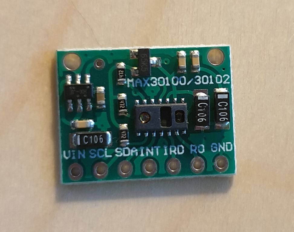
This afternoon I received a couple of MAX30100 sensors that I ordered some days before (44 days, China, COVID19, …)
MAX30100 Sensor Board
The board is quite easy to connect: it has an I2C interface and you even don’t need the INT pin, so all you have to do is wiring the SDA and SCL pins.
I used D22 and D21 pins in my ESP32 MCU, as they are also used for I2C_SDA and I2C_SCL interfacing (checkout pinout diagram here)
Summarizing, the pins you need to connect are:
ESP32 GND to SENSOR GND
ESP32 3.3 to SENSOR VIN
ESP32 D22 to SENSOR SDA
ESP32 D21 to SENSOR SCL
Once you have all the pins connected it’s software time.
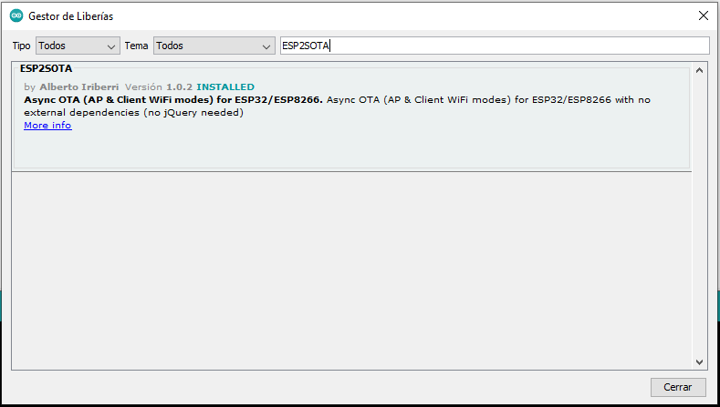
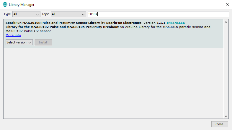
In Arduino IDE, select Manage Libraries and install the Sparkfun MAX3010X Library
After that, you are ready to open any of the examples provided with the library and test the module.
Probably you will notice that doesn’t work correctly. It seems to initialize the module correctly and even it starts to make some measurements. You even would think that is working for a few seconds, but it isn’t.
The behaviour, at least in my case, is the next:
The module initialize with a SUCESS status
It lights on the red led
You put your finger over the sensor
It starts measuring, but after a second the red led goes off
It seems to measure intermittently
If this is your case, don’t waste your time. I was searching for troubleshootings and all I found was replacing the inbuilt 4K7 resistors or bypassing the voltage limiter in the sensor board. Don’t do it, it is not a problem of pull-up resistors.
I decided then to try with an ESP8266 MCU and this is the result:
The sensor board works fine, so probably it is a problem of compatibility between the library and ESP32.
The sensor measures heart rate and SpO2. I only used the heartBeat event to light the led to show that it works.
Some of the ESP32 development boards provide a 3.7 Ion-Li battery charger what is an advantage when we want to get a device with the minimum number of components.
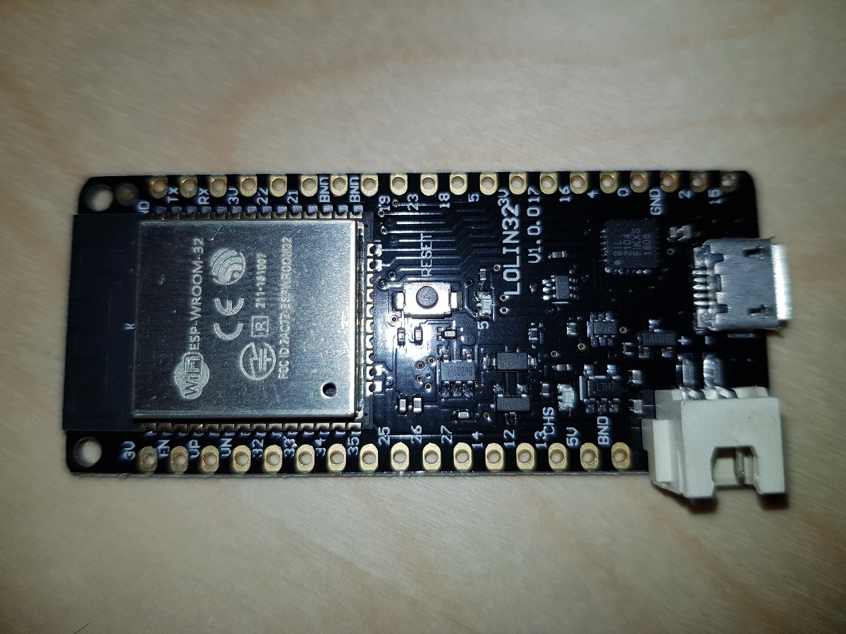
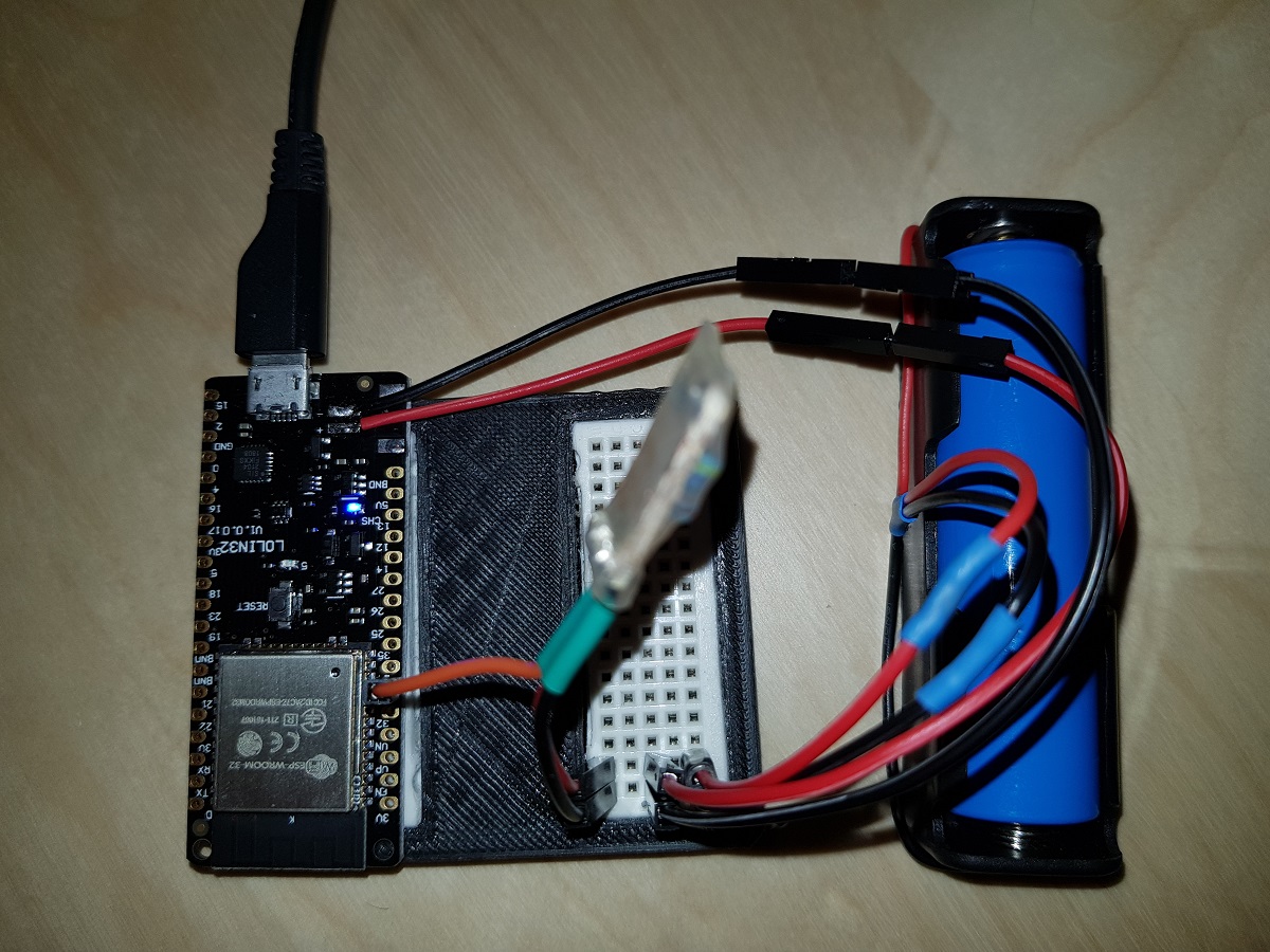
One of these boards is Wemos Lolin 32 (with battery charger) which costs about 7$ in eBay.
Wemos Lolin 32
When a battery is plugged in and the board is connected to a power source via the USB connector, the battery starts being charged.
As the ESP32 board counts with several ADC pins, we can use one of them to check the voltage in between the two battery terminals. The only issue with this is that ADC pins expect voltages between 0 and 3.3 volts and our Ion-Li battery voltage range may reach 4.2 volts.
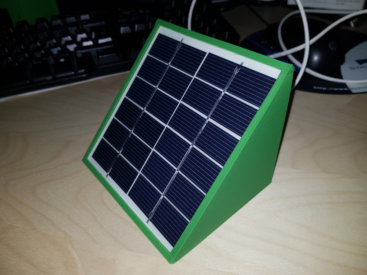
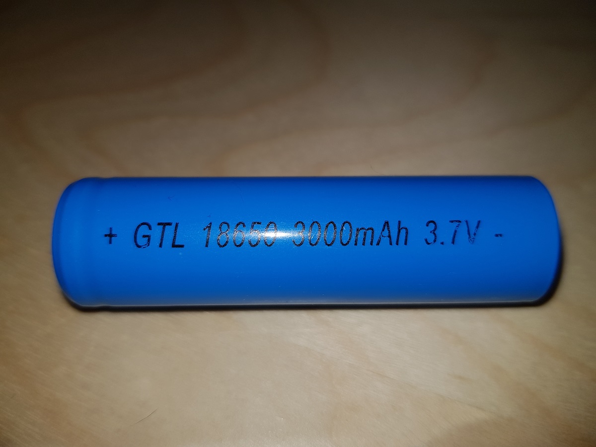
18650 Ion-Li Battery
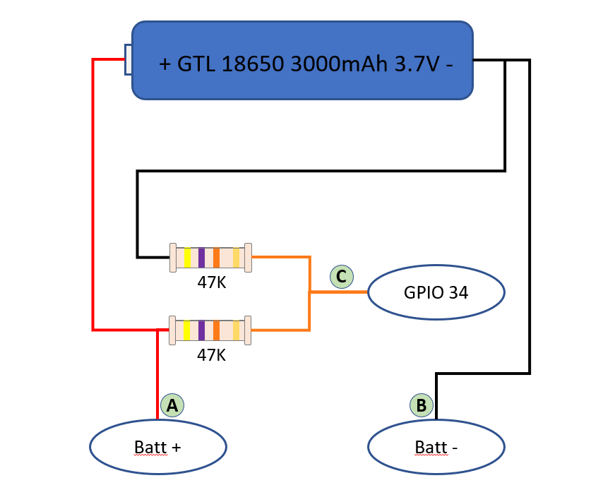
The solution to that is connecting a voltage divider to the battery, so we can divide the volts by 2 and the maximum value will be about 2.1 volts.
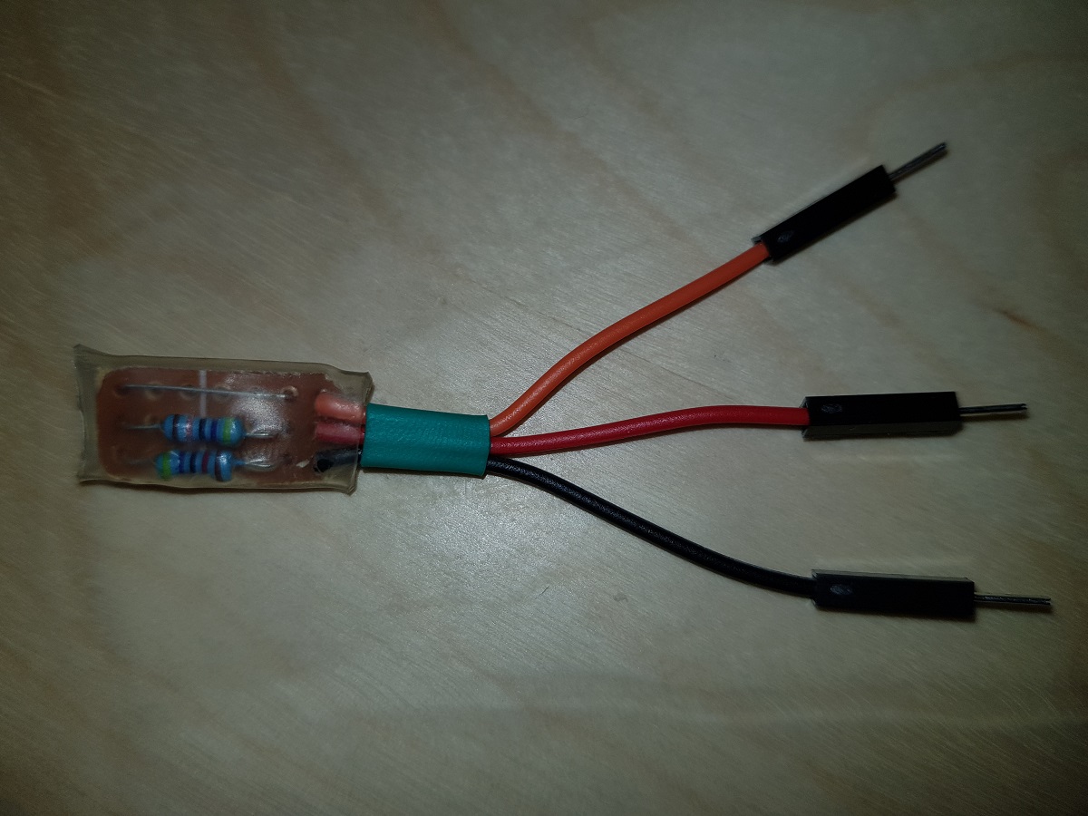
Voltage Divider SchemaVoltage Divider
Our voltage divider is built of two 47KΩ resistors. The total impedance between positive and negative terminals will be 94KΩ and that means a current of less than 5 50μA (microamperes, not milliamperes).(Thanks Jonathan)
Voltage Divider mounted on Lolin 32
With this, we can measure the voltage applied in GPIO34 (or any other ADC pins of our ESP32) and then, based on a conversion table, calculate the charge level of the battery.
First, we will get the value of ADC pin. This value may vary from 0 to 4096 depending on the voltage applied to it from 0V to 3.3V. So we can establish a constant to calculate the voltage applied to the pin based on its value. This constant, theoretically, will be 3300 / 4096 = 0.8056.
As we are applying a voltage divider and the voltage applied to the pin is half the voltage of the battery, our constant should be 0.8056 x 2 = 1.6113.
This means, for each unit in ADC pin we have 1.6113 mVolts applied to it.
For instance, if we read the value of the ADC pin and get 2,543, then the voltage applied to the pin should be 2,453 x 1.6113 = 3,952V = 3.95V
ADC pins are not that precise, so the value of our constant should be adjusted to a level we consider it is valid for our components. In my case, after doing some testings I have concluded that the best value for the conversion factor is 1.7.
As I mentioned before, calculating the charge level is a direct translation from the voltage we obtained to a charge level by using a table.
All the code to make these calculations is contained in a library I have created for that purpose. You can find it in Github at Pangodream_18650CL.
All you have to do is downloading the .zip file and add it to Arduino IDE.
There is an example of using the library:
#include <Pangodream_18650_CL.h>

//#define ADC_PIN 34
//#define CONV_FACTOR 1.7
//#define READS 20

Pangodream_18650_CL BL;
/**
 * If you need to change default values you can use it as
 * Pangodream_18650_CL BL(ADC_PIN, CONV_FACTOR, READS);
 */

void setup() {
  Serial.begin(115200);
}

void loop() {
  Serial.print("Value from pin: ");
  Serial.println(analogRead(34));
  Serial.print("Average value from pin: ");
  Serial.println(BL.pinRead());
  Serial.print("Volts: ");
  Serial.println(BL.getBatteryVolts());
  Serial.print("Charge level: ");
  Serial.println(BL.getBatteryChargeLevel());
  Serial.println("");
  delay(1000);
}
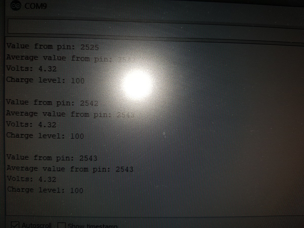
And if everything works, it should display something like this on your serial terminal:
After trying several options that I found on the web, I chose this one as the better to connect an ESP32 to an ILI9341 TFT display.
ESP32
ILI9341
3V3
VCC
GND
GND
D15
CS
D2
RESET
D4
D/C
D23
MOSI
D18
SCK
Not connected
MISO
3V3 (***or D19)
LED
The code:
/**
 * ILI9341 TFT libraries and resources
 */
const int TFT_CS = 15;
const int TFT_DC = 4;
const int TFT_MOSI = 23;
const int TFT_SLK = 18;
const int TFT_RST = 2;
const int TFT_LED = 19;

#include "SPI.h"
#include "Adafruit_GFX.h"
#include "Adafruit_ILI9341.h"
Adafruit_ILI9341 tft = Adafruit_ILI9341(TFT_CS, TFT_DC, TFT_MOSI, TFT_SLK, TFT_RST);

void setup() {
  tft.begin();
  tft.setRotation(3); //Landscape orientation
}
The reason for the two possibilities for the LED pin is the next:
If you connect LED pin directly to 3V3 you will get maximum brightness in your screen. LED pin controls the backlight of your TFT display.
In my case, I didn’t want to have max brightness but I wanted to control the intensity based on ambient light, so I decided to connect LED pin to any of the IO pins of the ESP32 (#19 in the showed example).
The code to control backlight intensity (once you have connected LED to pin D19) is as follows:
Inserting the code above allows you to set the backlight intensity at any point just invoking setBGLuminosity() function passing a value between 0 and 255.
This website uses cookies to improve your experience. We'll assume you're ok with this, but you can opt-out if you wish.AcceptReject
Privacy & Cookies Policy
Privacy Overview
This website uses cookies to improve your experience while you navigate through the website. Out of these, the cookies that are categorized as necessary are stored on your browser as they are essential for the working of basic functionalities of the website. We also use third-party cookies that help us analyze and understand how you use this website. These cookies will be stored in your browser only with your consent. You also have the option to opt-out of these cookies. But opting out of some of these cookies may affect your browsing experience.
Necessary cookies are absolutely essential for the website to function properly. This category only includes cookies that ensures basic functionalities and security features of the website. These cookies do not store any personal information.
Any cookies that may not be particularly necessary for the website to function and is used specifically to collect user personal data via analytics, ads, other embedded contents are termed as non-necessary cookies. It is mandatory to procure user consent prior to running these cookies on your website.