Some of the ESP32 development boards provide a 3.7 Ion-Li battery charger what is an advantage when we want to get a device with the minimum number of components.
One of these boards is Wemos Lolin 32 (with battery charger) which costs about 7$ in eBay.
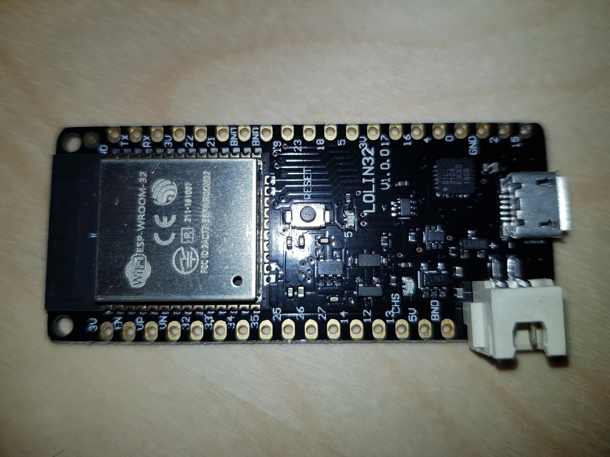
When a battery is plugged in and the board is connected to a power source via the USB connector, the battery starts being charged.
As the ESP32 board counts with several ADC pins, we can use one of them to check the voltage in between the two battery terminals. The only issue with this is that ADC pins expect voltages between 0 and 3.3 volts and our Ion-Li battery voltage range may reach 4.2 volts.
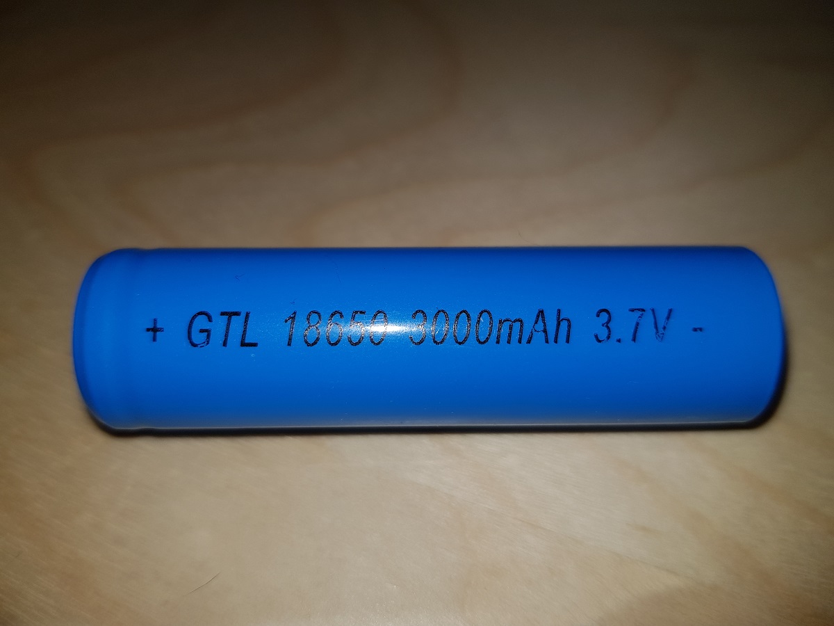
The solution to that is connecting a voltage divider to the battery, so we can divide the volts by 2 and the maximum value will be about 2.1 volts.
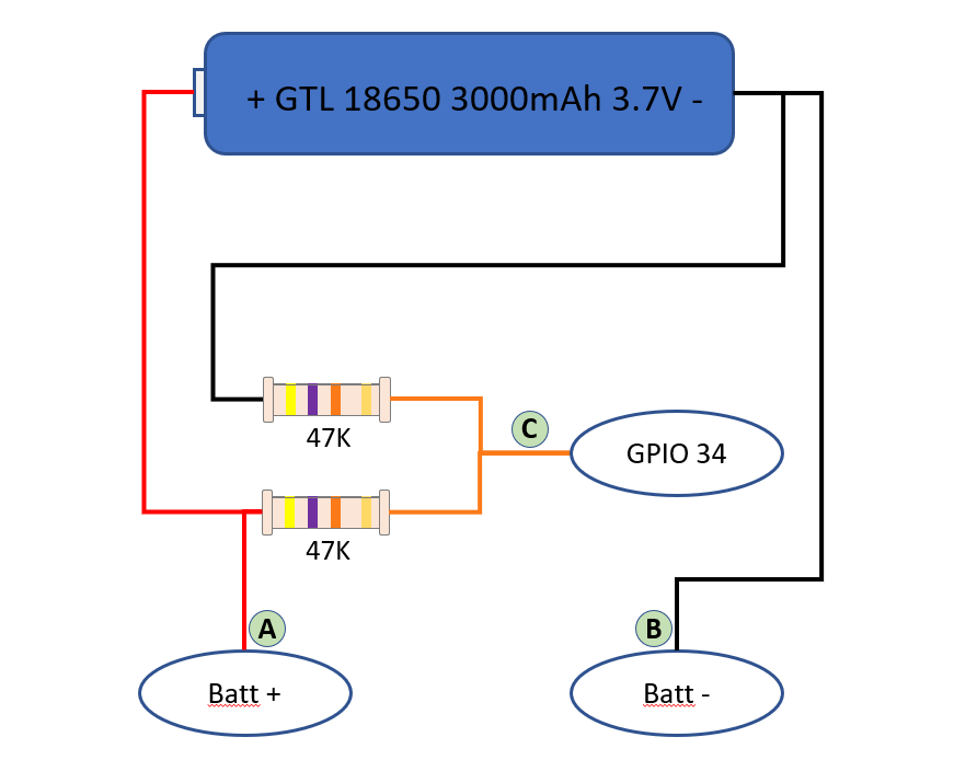
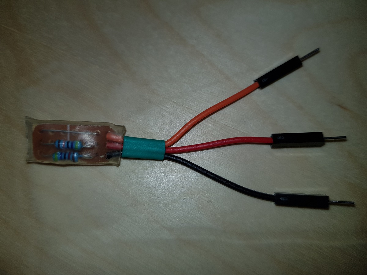
Our voltage divider is built of two 47KΩ resistors. The total impedance between positive and negative terminals will be 94KΩ and that means a current of less than 5 50μA (microamperes, not milliamperes). (Thanks Jonathan)
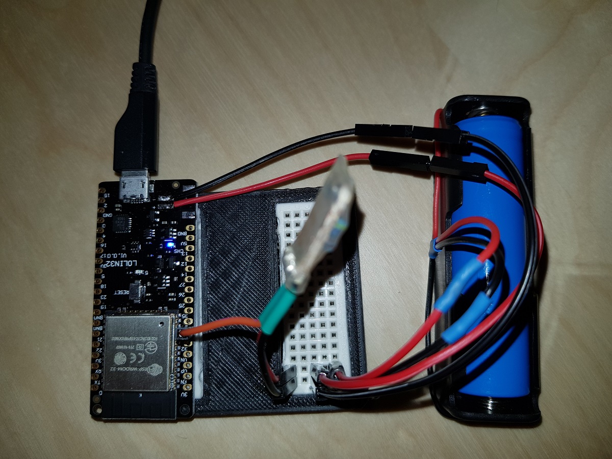
With this, we can measure the voltage applied in GPIO34 (or any other ADC pins of our ESP32) and then, based on a conversion table, calculate the charge level of the battery.
First, we will get the value of ADC pin. This value may vary from 0 to 4096 depending on the voltage applied to it from 0V to 3.3V. So we can establish a constant to calculate the voltage applied to the pin based on its value. This constant, theoretically, will be 3300 / 4096 = 0.8056.
As we are applying a voltage divider and the voltage applied to the pin is half the voltage of the battery, our constant should be 0.8056 x 2 = 1.6113.
This means, for each unit in ADC pin we have 1.6113 mVolts applied to it.
For instance, if we read the value of the ADC pin and get 2,543, then the voltage applied to the pin should be 2,453 x 1.6113 = 3,952V = 3.95V
ADC pins are not that precise, so the value of our constant should be adjusted to a level we consider it is valid for our components. In my case, after doing some testings I have concluded that the best value for the conversion factor is 1.7.
As I mentioned before, calculating the charge level is a direct translation from the voltage we obtained to a charge level by using a table.
All the code to make these calculations is contained in a library I have created for that purpose. You can find it in Github at Pangodream_18650CL.
All you have to do is downloading the .zip file and add it to Arduino IDE.
There is an example of using the library:
#include <Pangodream_18650_CL.h>

//#define ADC_PIN 34
//#define CONV_FACTOR 1.7
//#define READS 20

Pangodream_18650_CL BL;
/**
 * If you need to change default values you can use it as
 * Pangodream_18650_CL BL(ADC_PIN, CONV_FACTOR, READS);
 */

void setup() {
  Serial.begin(115200);
}

void loop() {
  Serial.print("Value from pin: ");
  Serial.println(analogRead(34));
  Serial.print("Average value from pin: ");
  Serial.println(BL.pinRead());
  Serial.print("Volts: ");
  Serial.println(BL.getBatteryVolts());
  Serial.print("Charge level: ");
  Serial.println(BL.getBatteryChargeLevel());
  Serial.println("");
  delay(1000);
}
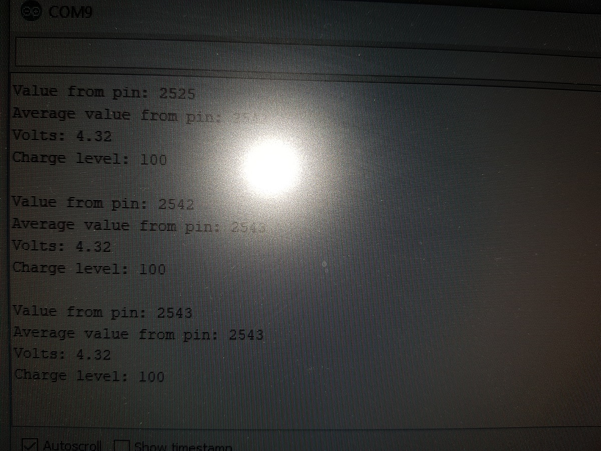
And if everything works, it should display something like this on your serial terminal:

Hi
Useful article, I just happened to spot that your current consumption calculation for the voltage divider is out by a factor of ten – you should say under 50 microamps, not under 5.
(1V / 1M = 1 microamp, so ~ 100k will be 10 times that.
Thanks a lot Jonathan!!! You are right!!
I’ve already modified the post.
Regards.
Nice post. The higher the resistance, the longer the battery last: do you know if trying with a much higher resistor values (let’s say two 470K resistors) will still make reliable measurements? I’m looking for ESP32 ADC input impedance value, but it seems that this information is not available.
Thanks Gabriele!!! 🙂
I guess it is not a good idea to increase the resistors value so much. I remember measuring a lot of noise in measurements even when using 47K resistors.
Please, if you try and achieve good results let me know.
Regards
I used 100K with flawless results.
Thanks for commenting David!!!
@David Kraft what CONV_FACTOR value did you use with 2 100k Ohm resistors?
This work to measure the includes battery? With out USB.
Hi, I was wondering if the charger of that board stops charging when the battery reaches it maximum capacity.
Thank you
tp4054 chip stops charging when the battery is full.
Thanks for commenting.
Hi, does it also have protection for deep discharge like the TP4056?
Where would I connect charging voltage (5V) when using solar panel and not USB?
Hi, I got this working. But now I want to see the batt value on my phone or computer when I connect the bluetooth device.
Any idea?
TIA
Newb here. Thanks for putting this piece together as well as the library. Can you explain to me how your battery, which is clearly labeled as 3.7v, might reach as high as 4.2v as you suggest at the top of your article?
Thanks!
3.7 is the “average” voltage of the battery. Charging it probably happens at around 4.2, and it will be around that voltage for a little while when it’s fully charged.
You can search and find charge/discharge curves for different types of batteries to figure out what voltages to expect.
Thanks for your help Gopiballava. Regards
Hi ,
Great job, Thank you.
Only a sugestion : could you introduce a custom factor that the user can use to set is own conversion factor ?
This can be usefull because i think that your library will be used when the power supply is diconnected , to send by mqtt a battery level.
Your calculation seems to be done by assuming the fact the power supply is allways connected.
I am wrong?
Regards
Didier
Hi, I got three esp32 , but every esp32 must set diffrent value (conversion factor). Is it my problem ? or esp32 is NOT good for DAC?
sorry, “ADC “
Hej Frank. This is a known problem with the esp32, especially the range below 0.2V and above 3V are affected. See https://github.com/e-tinkers/esp32-adc-calibrate for the linearity and possible optimisations.
However, if you need a real precise measurement, you are better off with a dedicated adc chip, i.e. ADS1115.
Hi, thank you I can measure the battery. Is there a way to detect if there is power at the USB. I want to detect when the power is off and it is running off the battery.
Hi, i’m using ESP12E with adc 0-1v. I read the ADC data, but I get fluctuating data of ADC
hi tried your code but my charging level is always 0 percent and analog read is between 1500-1600 only
Did it with 2 100k resistors (current draw is about 20ma) with excellent results.
Used factor of 1.832 (changed in library).
I used pin 36 (changed in library) on Lolin32 Lite because this pin is marked VP which is supposed to give cleaner ADC.
I’m using a 3.7v 500mah lipo pack, and I’m going to monitor carefully the battery capacity percentages displayed.
Anyway, thanks a lot for the easy to use library!
Thank you very much Ian!!!! 🙂
Your welcome. The thanks goes to you!!!!
Your article is excellent and your library is pretty neat.
Once I saw that it works, I made a neat cut-down battery plug module, with minimum cable wire (to reduce current draw), short-lead resistors, heat-shrinked the whole thing, its now tiny & neat!
Anyway upon re-measuring against multimeter, I finally changed the factor to 1.783 which seems good.
Still going to check capacity readings.
A massive thanks again!!!
Hi, great post! I am using a solar panel to charge my battery. The solar at full sun is about 8.03v. Using a MCP73871 to control the charge. All working perfectly reading the battery voltage. What resistors in the voltage divider would you suggest for the solar monitoring circuit and what conversion factor?
Thanks again!!
How did you connect the panel to the board to charge to battery using the onboard charger?
Hello,
Great post and a valueable library.
I set custom values, but the percentage stays at 100%, even when the battery voltage is changing.
Is it possible that there is something wrong in the library?
Thanks,
Mark
hi i use your library and everything works. I added your library to ESP32-BLE-GAMEPAD. At the end of the loop I added bleGamepad.setBatteryLevel (BL.getBatteryChargeLevel ()); Windows detects the battery% on connection but does not refresh this value later. I need to remove and add a device for the battery value to update. Should I add anything else to the code? Sorry, but I just started learning Arduino IDE
Hello, thanks for this nice article. I’m wondering if the little charging LED indicator (the red light) that turns on when it’s charging will turn off when the battery is fully charged, or if the battery will start to overcharge. I’m using what appears to be the same exact ESP32 that you are.
Thank you
– Cam
Found a conversion factor around 1.75 working perfect.
And i am using 100K ohm.
Thank you so much for this article!
Thank you for commenting and share your experience!!!
These LOLIN boards report the battery voltage on ADC pin 35 by default. Maybe you already know this and I’m missing the point 🙂
lolin32’s do not report on pin 35, only the newer lolin d32. That one has less pin’s and the battery connector is pointing same as usb instead of sideways.
Other Wemos boards like the LOLIN D32 have this feature, but I don’t believe the regular LOLIN32 does.
Congratulations. Reallly an amazing article. I am trying this in a Lilygo t-Display s3, which has the CAD pin for batteries in the GPIO04. For the time being, it is working really well, but it turns to be a little unstable in the readings.
I´m afraid it can be because of the type of batteries that I’m using, but neverthless I will find the key for the issue soon.
Thanks a lot for this. Really helps.
good jop sir
if i used the lipo battery in which you used in the video,the code is the same or it is different.
and is not please put here the correct code.
thank you
Uff spectacular work!
Your library really help me with my project
thanks!!!
i’ve tried with 100k ohm resistor. but the result of charge level is not mapped from 0-100 but 0-10, can you please help me sir?