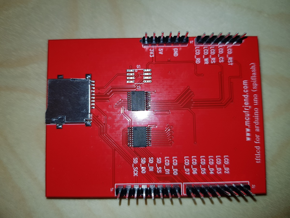
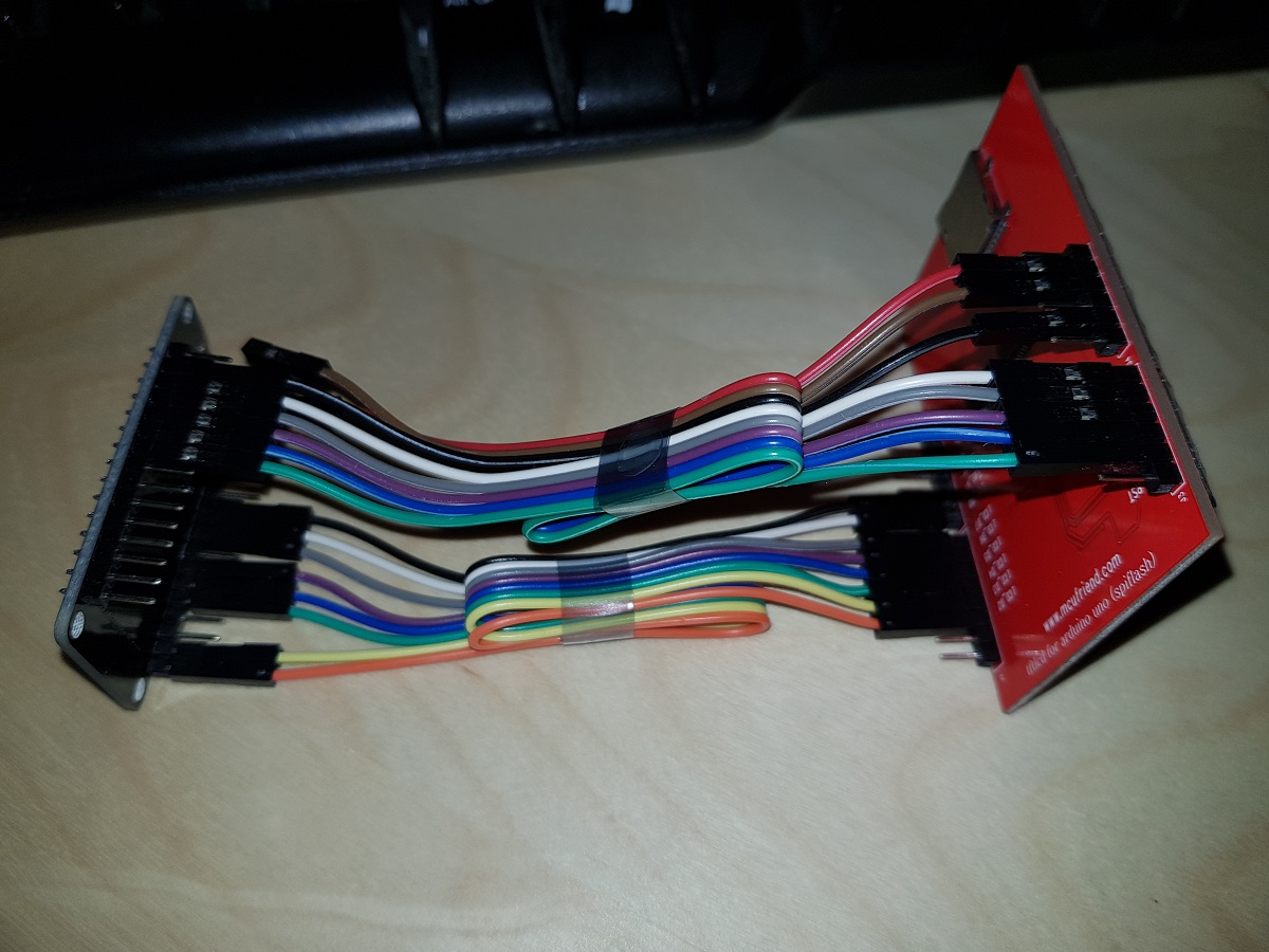
Today I’ve received two ILI9341 TFT screens that I ordered some weeks ago. These screens are in fact a shield designed for Arduino Uno but they work nicely when connected to other developer boards and the price is amazingly cheap: just US$4.
In this case, we will connect the screen to an ESP32 Dev Board.
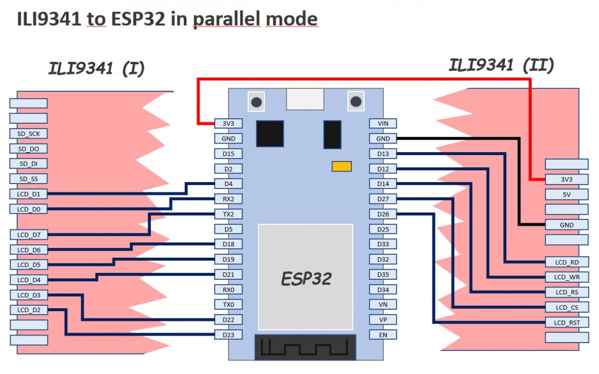
The pins are configured in a slightly different way than other examples you could find in the web: I’ve tried to minimize mistakes because we will use 13 pins so I thought the best way would be to use as much as possible consecutive pins.
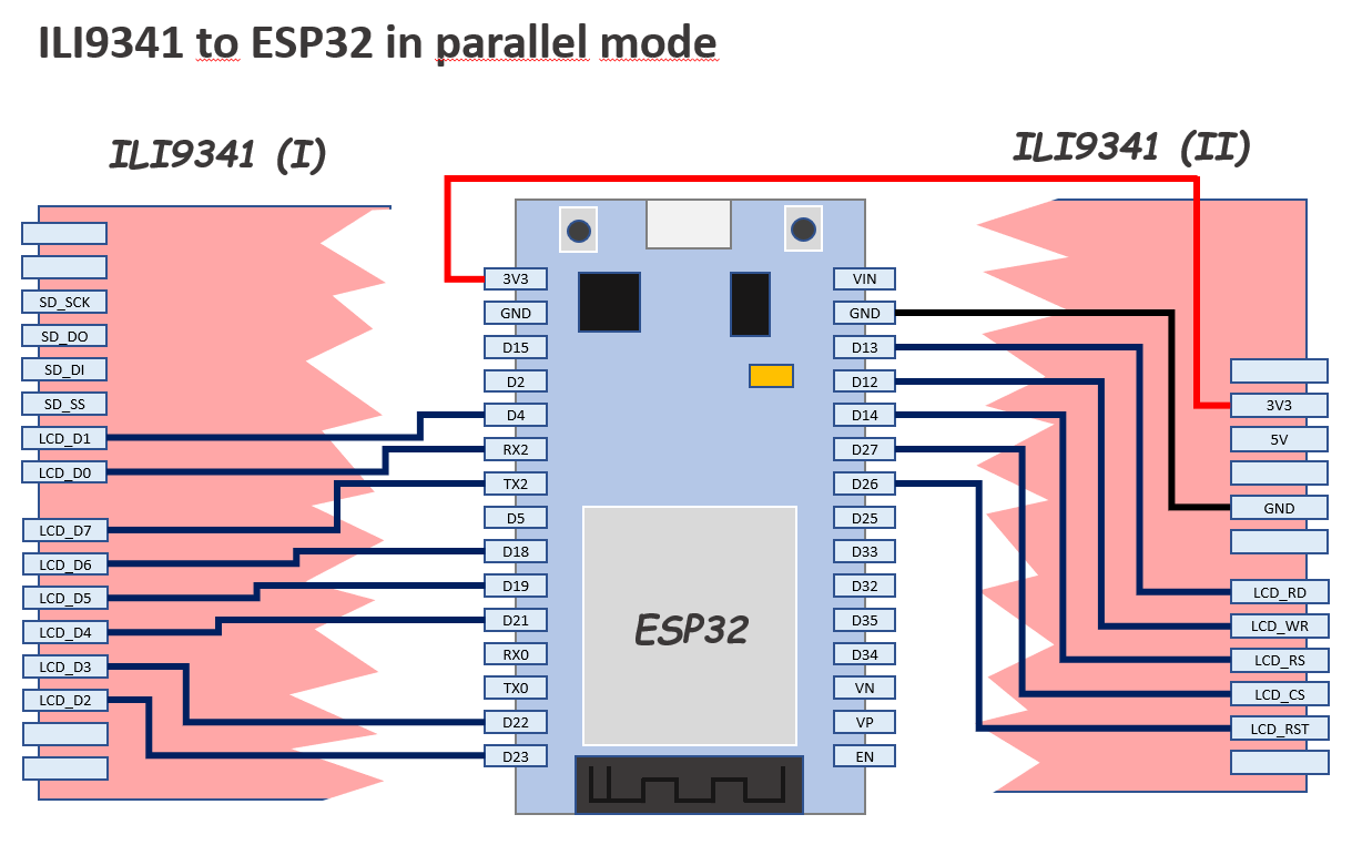
You can also connect the ILI9341 using only 4 IO pins (not this model), but the refresh/painting speed is not comparable.
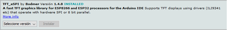
The library we will use is TFT_eSPI library by Bodmer and our only purpose by the moment will be executing an example demo script successfully.
During testing, you can connect TFT 3V3 pin directly to ESP32 3V3 pin, but do it only during a short period of time because the current drawn by the screen LEDs is 134mA and you will notice how the LEDs and the Development Board voltage limiter will become hot.
A 22Ω resistor (not 220) between the two 3V3 pins it’s enough to reduce the current to 23mA and though the screen is not the brightest one in the world I think it is enough for testing purposes.
Once you have finished the connection of the pins as described in the diagram above, you can install the TFT_eSPI library if you don’t have it already installed.
Open Arduino IDE, go to Library Manager and in the search box type TFT_eSPI. In the results list, look for the next and install it.
Now you have the library installed you have to configure the IO pins where we have connected our screen. Other libraries use the definition of constants at the top of each sketch to do this, but TFT_eSPI uses a common file to define the configuration.
Find in your Arduino installation the file called User_Setup.h
It should be located in a path equivalent to this:
[Arduino Folder]/libraries/TFT_eSPI/User_Setup.h
Now, copy the file for backup purposes and edit the original to place inside it this following content (replacing all the previous content):
// See SetupX_Template.h for all options available

#define ESP32_PARALLEL


#define ILI9341_DRIVER


// ESP32 pins used for the parallel interface TFT
#define TFT_CS   27  // Chip select control pin
#define TFT_DC   14  // Data Command control pin - must use a pin in the range 0-31
#define TFT_RST  26  // Reset pin

#define TFT_WR   12  // Write strobe control pin - must use a pin in the range 0-31
#define TFT_RD   13

#define TFT_D0   16  // Must use pins in the range 0-31 for the data bus
#define TFT_D1   4  // so a single register write sets/clears all bits
#define TFT_D2   23
#define TFT_D3   22
#define TFT_D4   21
#define TFT_D5   19
#define TFT_D6   18
#define TFT_D7   17


#define LOAD_GLCD   // Font 1. Original Adafruit 8 pixel font needs ~1820 bytes in FLASH
#define LOAD_FONT2  // Font 2. Small 16 pixel high font, needs ~3534 bytes in FLASH, 96 characters
#define LOAD_FONT4  // Font 4. Medium 26 pixel high font, needs ~5848 bytes in FLASH, 96 characters
#define LOAD_FONT6  // Font 6. Large 48 pixel font, needs ~2666 bytes in FLASH, only characters 1234567890:-.apm
#define LOAD_FONT7  // Font 7. 7 segment 48 pixel font, needs ~2438 bytes in FLASH, only characters 1234567890:.
#define LOAD_FONT8  // Font 8. Large 75 pixel font needs ~3256 bytes in FLASH, only characters 1234567890:-.
#define LOAD_GFXFF  // FreeFonts. Include access to the 48 Adafruit_GFX free fonts FF1 to FF48 and custom fonts

#define SMOOTH_FONT
Save the file and go back to Arduino IDE.
Open the example sketch UTFT_demo (it is under File / Examples / TFT_eSPI / 320 x 240 / UTFT_demo)
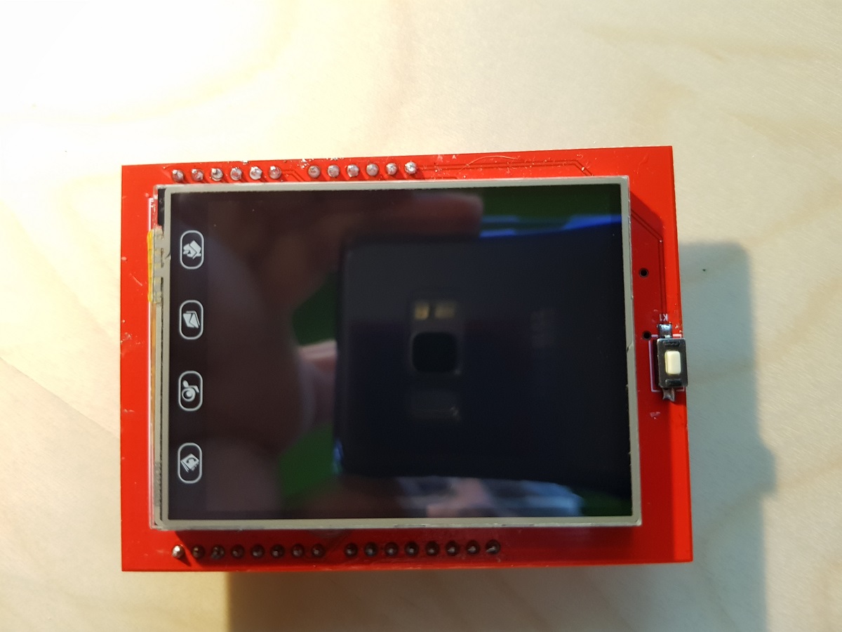
At this point, you can compile and upload the sketch to your ESP32. If everything went ok you should see some graphics, backgrounds and texts appearing in your TFT screen. Otherwise please review carefully the IO pins configuration (hard and soft).
If it works, probably you’ll see the results like in a mirror. To solve this, go to the sketch and edit the line that sets the screen orientation. This is done in the setup function.
void setup()
{
  randomSeed(analogRead(A0));
// Setup the LCD
  myGLCD.init();
  //myGLCD.setRotation(1); //Comment out this one and insert the one below
  myGLCD.setRotation(7);
}
The result now should look like this