Since I was a child I loved gadgets, electronic parts, wires, opening every machine that fell into my hands.
My job is related to technology, but nothing of hardware in it, just software. I work for an advertising company and we don’t produce anything you can touch with your hands. Though I am an enthusiast of coding and designing software I am always buying cheap components, electrical instrumentation and from time to time I ‘produce’ some little things for the home, but I never have enough time to make interesting things.
During years I have been reading blog entries at hackaday.com. The things they talk about are those things I would love to be making the whole day.
Some months ago I started walking with pain in one of my feet. Things became more complicated and finally, I had surgery and had to stay at home during some months. That means a big issue for me because of my job but as someone said “problems can become opportunities” and that’s what it happened… now I have a bunch of time to think and study.
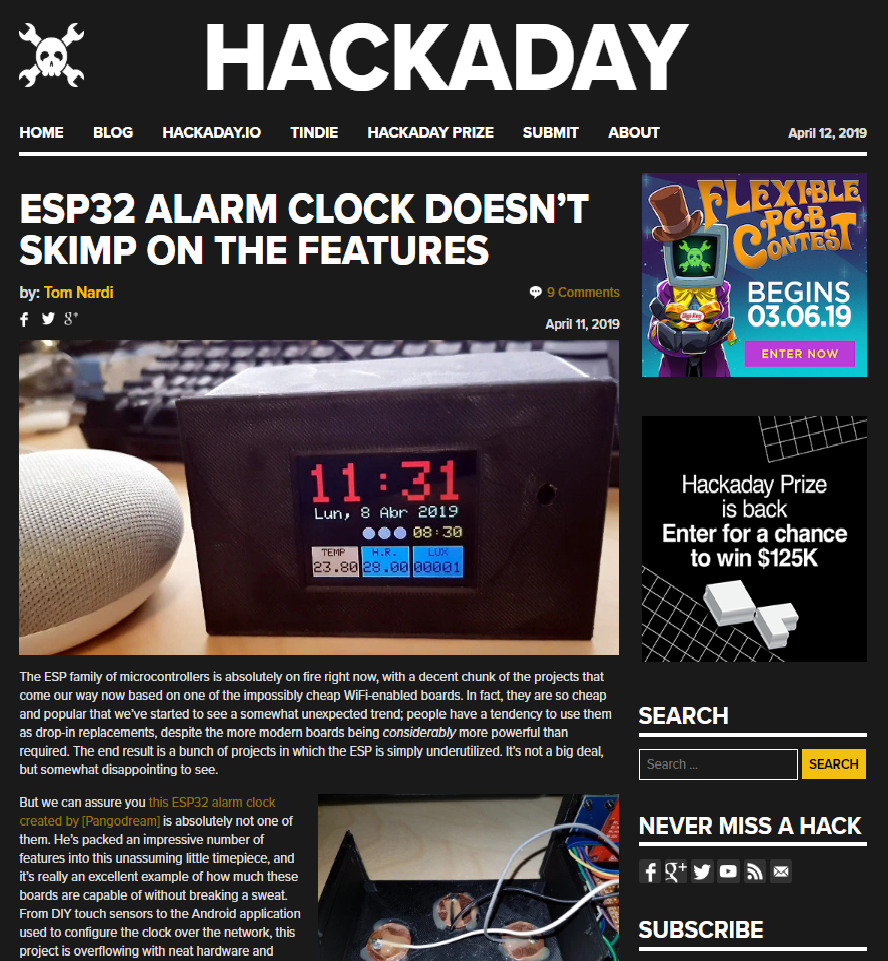
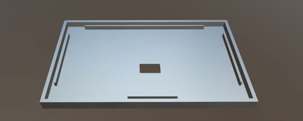
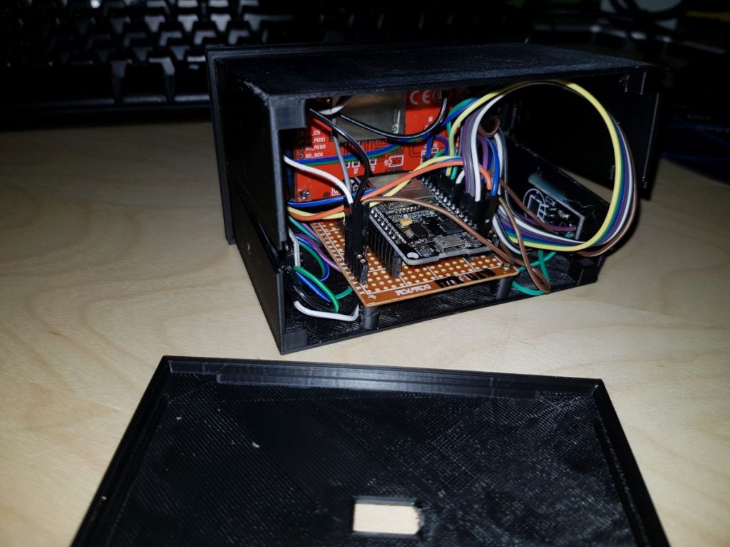
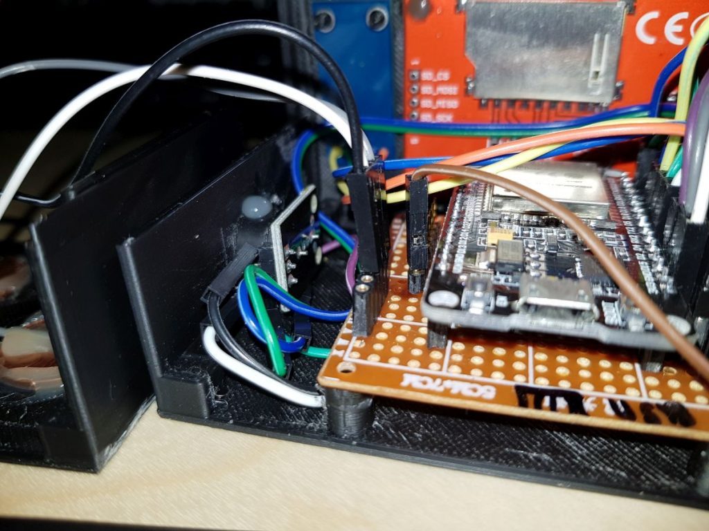
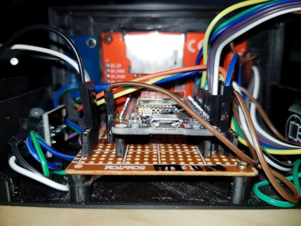
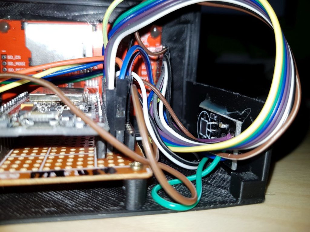
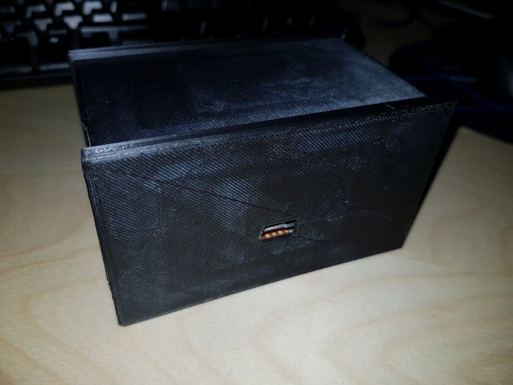
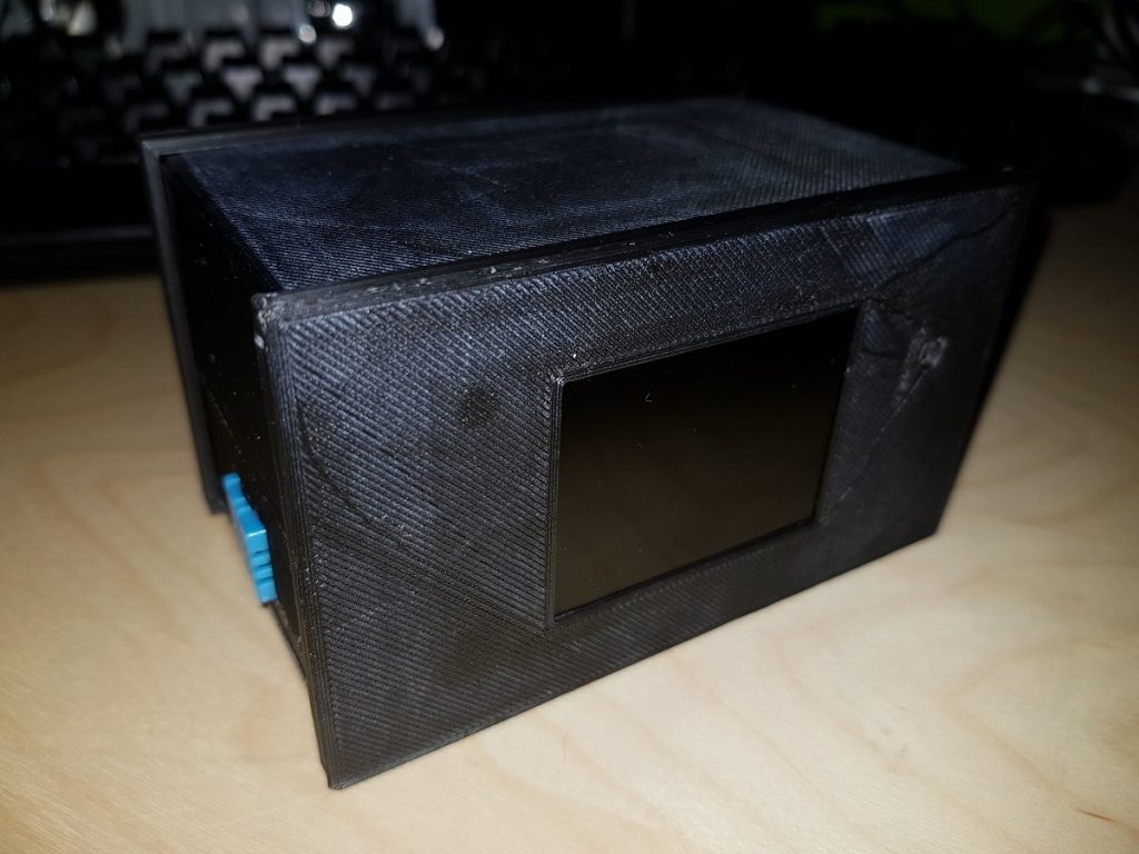
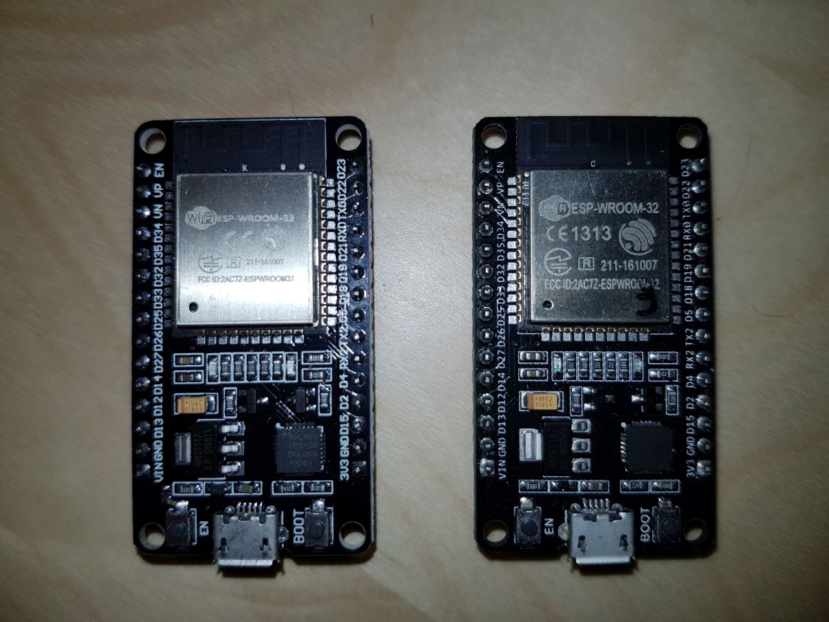
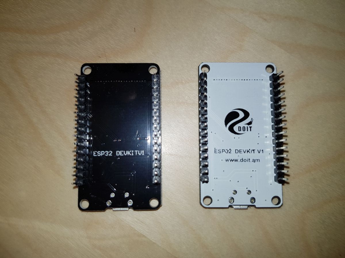
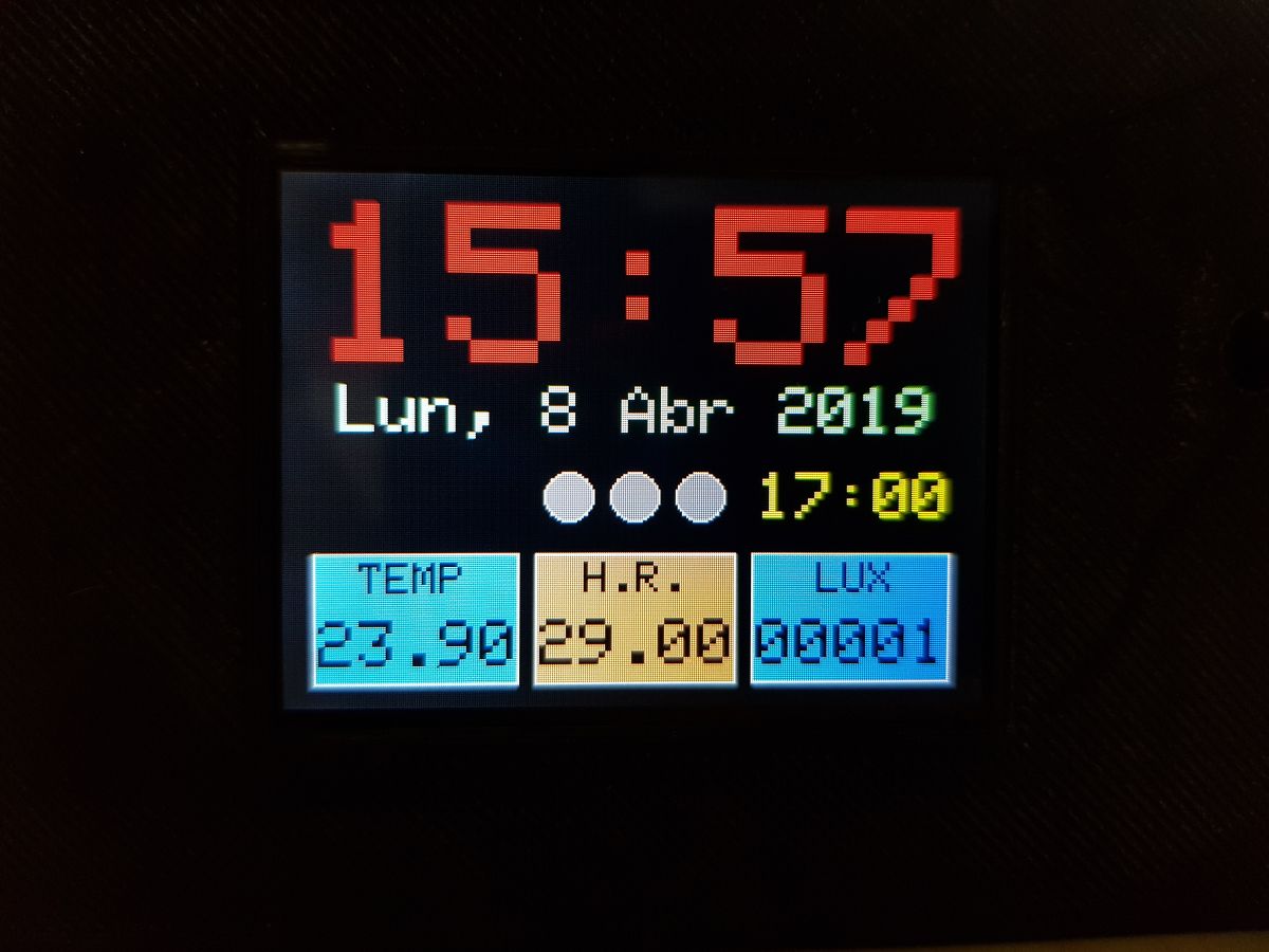
As I had a lot of components waiting for me, I decided to buy a 3D printer and make something. Three weeks ago I started thinking on an Alarm Clock and today that thing is Claudio.
Some days ago I submitted the Github repository link to hackaday.com thinking they would ignore it but they replied my email and told me their intention to publish a post about it. I felt really proud and happy.
Today they made my day. Thanks, Tom! 😀