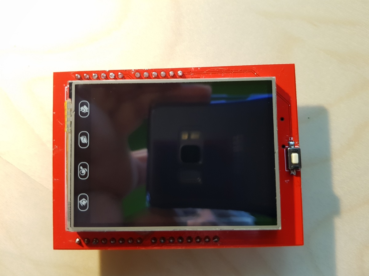
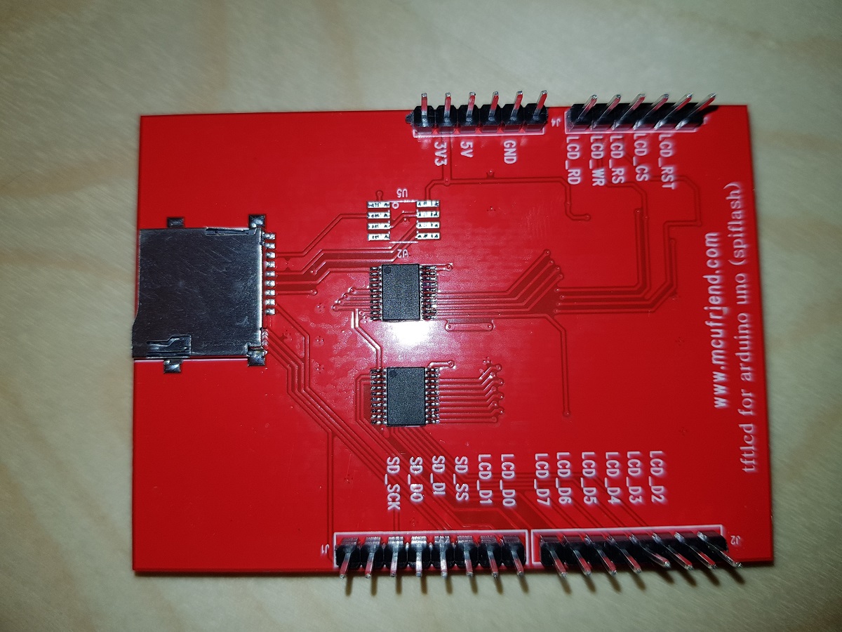
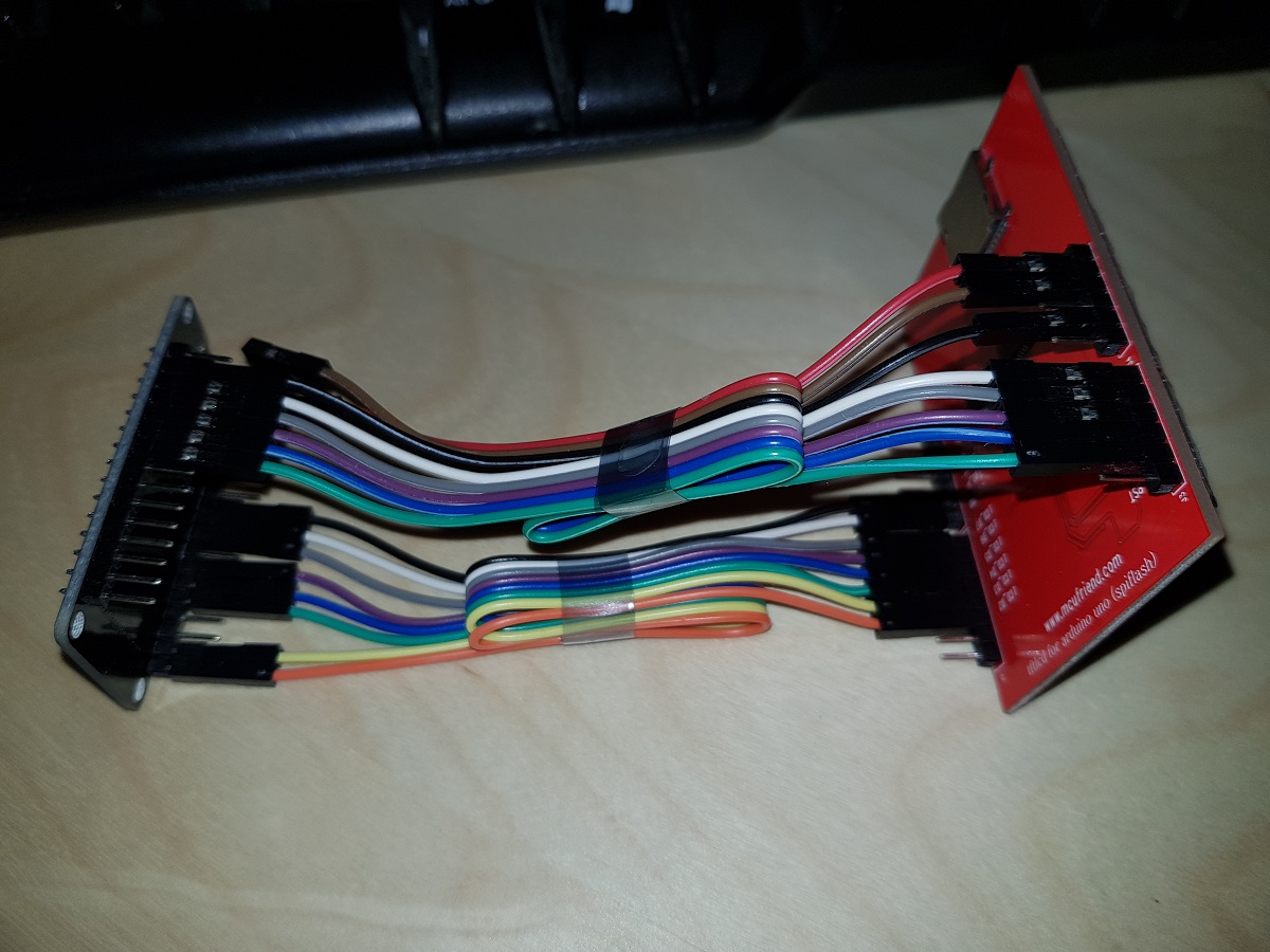
Today I’ve received two ILI9341 TFT screens that I ordered some weeks ago. These screens are in fact a shield designed for Arduino Uno but they work nicely when connected to other developer boards and the price is amazingly cheap: just US$4.
In this case, we will connect the screen to an ESP32 Dev Board.
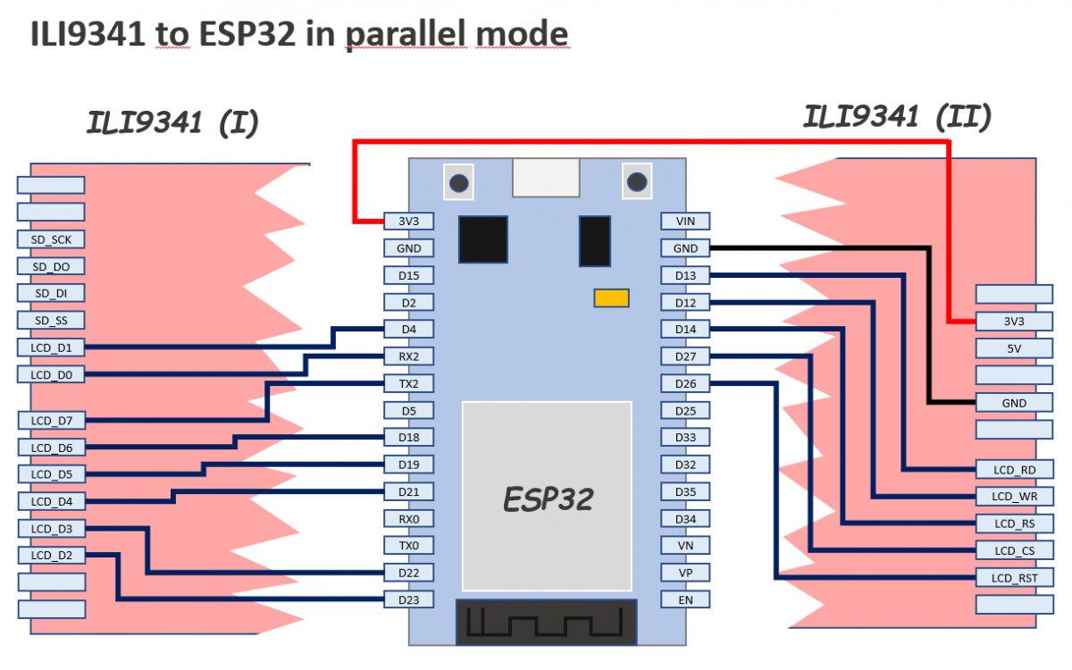
The pins are configured in a slightly different way than other examples you could find in the web: I’ve tried to minimize mistakes because we will use 13 pins so I thought the best way would be to use as much as possible consecutive pins.
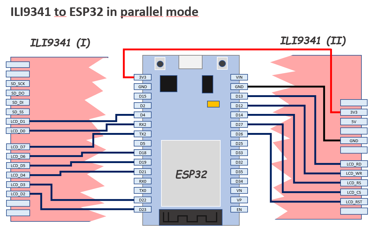
You can also connect the ILI9341 using only 4 IO pins (not this model), but the refresh/painting speed is not comparable.
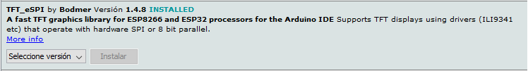
The library we will use is TFT_eSPI library by Bodmer and our only purpose by the moment will be executing an example demo script successfully.
During testing, you can connect TFT 3V3 pin directly to ESP32 3V3 pin, but do it only during a short period of time because the current drawn by the screen LEDs is 134mA and you will notice how the LEDs and the Development Board voltage limiter will become hot.
A 22Ω resistor (not 220) between the two 3V3 pins it’s enough to reduce the current to 23mA and though the screen is not the brightest one in the world I think it is enough for testing purposes.
Once you have finished the connection of the pins as described in the diagram above, you can install the TFT_eSPI library if you don’t have it already installed.
Open Arduino IDE, go to Library Manager and in the search box type TFT_eSPI. In the results list, look for the next and install it.
Now you have the library installed you have to configure the IO pins where we have connected our screen. Other libraries use the definition of constants at the top of each sketch to do this, but TFT_eSPI uses a common file to define the configuration.
Find in your Arduino installation the file called User_Setup.h
It should be located in a path equivalent to this:
[Arduino Folder]/libraries/TFT_eSPI/User_Setup.h
Now, copy the file for backup purposes and edit the original to place inside it this following content (replacing all the previous content):
// See SetupX_Template.h for all options available

#define ESP32_PARALLEL


#define ILI9341_DRIVER


// ESP32 pins used for the parallel interface TFT
#define TFT_CS   27  // Chip select control pin
#define TFT_DC   14  // Data Command control pin - must use a pin in the range 0-31
#define TFT_RST  26  // Reset pin

#define TFT_WR   12  // Write strobe control pin - must use a pin in the range 0-31
#define TFT_RD   13

#define TFT_D0   16  // Must use pins in the range 0-31 for the data bus
#define TFT_D1   4  // so a single register write sets/clears all bits
#define TFT_D2   23
#define TFT_D3   22
#define TFT_D4   21
#define TFT_D5   19
#define TFT_D6   18
#define TFT_D7   17


#define LOAD_GLCD   // Font 1. Original Adafruit 8 pixel font needs ~1820 bytes in FLASH
#define LOAD_FONT2  // Font 2. Small 16 pixel high font, needs ~3534 bytes in FLASH, 96 characters
#define LOAD_FONT4  // Font 4. Medium 26 pixel high font, needs ~5848 bytes in FLASH, 96 characters
#define LOAD_FONT6  // Font 6. Large 48 pixel font, needs ~2666 bytes in FLASH, only characters 1234567890:-.apm
#define LOAD_FONT7  // Font 7. 7 segment 48 pixel font, needs ~2438 bytes in FLASH, only characters 1234567890:.
#define LOAD_FONT8  // Font 8. Large 75 pixel font needs ~3256 bytes in FLASH, only characters 1234567890:-.
#define LOAD_GFXFF  // FreeFonts. Include access to the 48 Adafruit_GFX free fonts FF1 to FF48 and custom fonts

#define SMOOTH_FONT
Save the file and go back to Arduino IDE.
Open the example sketch UTFT_demo (it is under File / Examples / TFT_eSPI / 320 x 240 / UTFT_demo)
At this point, you can compile and upload the sketch to your ESP32. If everything went ok you should see some graphics, backgrounds and texts appearing in your TFT screen. Otherwise please review carefully the IO pins configuration (hard and soft).
If it works, probably you’ll see the results like in a mirror. To solve this, go to the sketch and edit the line that sets the screen orientation. This is done in the setup function.
void setup()
{
  randomSeed(analogRead(A0));
// Setup the LCD
  myGLCD.init();
  //myGLCD.setRotation(1); //Comment out this one and insert the one below
  myGLCD.setRotation(7);
}
The result now should look like this
thanks for that tutorial, it did the trick for me.
hi, can you please make a video?
Sorry, no, I can’t
Thanks a lot
hay… how to setting touchscreen?
Sorry I didn’t cover that in my testing.
I guess same way as on arduino. YP and XM pins are shared on those TFT touchscreen shields.
Run mcufriend touch calibration script from examples, copy and paste setup lines from serial output to your sketch.
Adafruit touchscreen lib reads values
TSPoint p = ts.getPoint();
then you have to restore mode for TFT control pins
pinMode(YP, OUTPUT); //restore shared pins
pinMode(XM, OUTPUT);
digitalWrite(YP, HIGH); //because TFT control pins
digitalWrite(XM, HIGH);
But haven’t tried it myself yet.
MERCI BEAUCOUP
Il n’y a pas de quoi 😉
Thank you very much for this precise and detailed procedure Alberto!
You’ve totally unblocked me and I’ll finally be able to move forward!
The display refresh is super fast. It’s great!
Merci infiniment 😉
It’s a pleasure receiving comments like this. Have a very nice day. 🙂
+1 from me too thnx
It doesn’t work in my TFT board. The screen only shows a lot of pixels of different colors, i don’t know if i made a mistake in the PINOUT configuration.. Can you help me?
Sorry, I wrote the post one year ago (1 year and 3 days ago) and honestly I don’t remember the details.
Is the TFT the same model?
Have you reviewed the pins?
The pins connection is quite straight the way I did it… so if its not a pinout issue you should review software configuration…
I made a mistake in the PINOUT connections… I’m sorry, but now my TOUCH isn’t working. Apparealy, I need to configure the Touch_CS port in the User_Setup, but i can make it work.
Thank you anyways
Good! I’m glad to hear that.
Thank you for replying Marlon. 🙂
Thank you very much, it is working. Do you know the way for to increase the bright? Thank you in advance.
You can connect the backlight led to 3.3 or 5 V pin with it’s appropriate resistor.
Sorry for the questions but I’m new in this topics, which one is the backlight led? I’m very grateful for your help. I was searching info but for this model I couldn’t find nothing about the backlight led.
Don’t worry. Try this:
Instead of connecting to 3V3, use 5V. To do that:
1.- Remove completely (from both sides) the wire that connects 3V3 pin in ESP32 to 3V3 pin in TFT (it is the red one in the schematic)
2.- Connect the previous wire to the opposite pin in ESP32 named Vin (which actually is 5V) to the 5V pin in TFT (the one next to 3V3)
It should look brighter now…
Amazing man!!! Thank you for your help and for to be patient. I’m exited!!!
Saludos from México!!!
Thank you for your comments Misael!!! 🙂
Viva México!!!
Hi Alberto, here with a new doubt, I need to use the ports Rx2 and Tx2 of the ESP32 for communication with Arduino Uno via serial, I tried with Rx0 and Tx0 but that not work, I think that ports are reserved for other function, I don’t understand completly the function for each one pin, then of that I tried change the wire connection for LCD_D0 with GPIO25 and LCD_D7 with GPIO15, but that didn’t work, I modified the file User_Setup.h with that changes, could you say me if is possible to release the ports RX2 and Tx2 ?
I was reading about this inconvinience, but I can’t implement a satisfactory solution yet.
Thank you in advance.
Misael
Hi Misael,
the development board you are using is this one?
https://www.pangodream.es/wp-content/uploads/2019/05/ESP32-DevKit.png
That’s correct Alberto, ESP32 with 30 pins.
You shouldn’t have any problem when changing the pins. Could you please try with pins D25 and D5….
Are you sure the modified file has been used for compilation?
And one more question, when you say it didn’t work, what was the issue? I mean, blank screen, unreadable content, ….
Thank you for your tutorial.
Just to inform you:
A fatal error occurred: Timed out waiting for packet content
A fatal error occurred: Timed out waiting for packet content
I’ve got this error trying to use with my esp32 devkit and the tft ili9341
Hi Junix,
your problem should be related to MCU programming. Based on my experience, try these to solve your problem:
– Check if you are able to upload a simple sketch to your MCU. Try with blink.ino one. The reason is that there are some boards that need your help (manually push switches during uploading)
– If the one above is not your issue, review the pinout. Probably you are using a pin needed for serial programming and that is a problem.
If you review all the steps and the pin wiring is the correct one… it should work.
Good luck, I know those moments when it seems it will never work…. but it always does it if you persevere. 🙂
I received the same error. I simply powered-down the display while downloading the ESP32. It could be a power quality issue if you’re running on USB power.
Disconnect LCD, upload code and then connect LCD. It’ll work.
Hi, i am always getting white screen, have checked HW connections they are ok and configuration file is ok too. Have checked LCD with ardunio it is ok
Hi,
did you found a solution?
I face the same trouble…
Same here a few years later
Hi,
First of all, thank you so much for providing this thread of help.
I have tried this connection by using ILI9486 instead of ILI9341. Made the changes in header file also. But it’s not working. Always showing the white screen only.
Thanks for commenting Abhishek.
I am afraid I cannot help you because I’ve never tried the display you mentioned in your comment. Hopefully someone else could help you….
I think there has something wrong on your work… I using ILI9486 also and it works for me. I just simply made a changes in User_Setup.h:
#define ILI9431_DRIVER
to:
#define ILI9486_DRIVER
Hey, thank you very much for this article! I finally got it to work 🙂
It didn’t work immediately, because there was this part written in Setup1_ILI9341.h:
//For Esp82x
#define TFT_CS PIN_D8 // Chip select control pin D8
#define TFT_DC PIN_D3 // Data Command control pin
#define TFT_RST PIN_D4 // Reset pin (could connect to NodeMCU RST, see next line)
#define TFT_RST -1 // Set TFT_RST to -1 if the display RESET is connected to NodeMCU RST or 3.3V
which overwrote my settings. So I commented it out and it worked fine 🙂
But my question would be: Have you ever tryed to use the sd card as well? I am insecure, wether the SPI bus is already used or not.
Thanks a lot for commenting Potato. 🙂
I’ve never tried the SD card functionality 🙁
great work many thanks ,by the way how to use ili9341 8bit parallel with lvgl and with touch,thanks.
Thank you very much!!!!
Good work 🙂 How can touch support be added to this?
Sorry, I dindn’t work on that.
Thanks for commenting.
thanks for that tutorial its really useful for my project
Can I use 6 bit only (D0 to D5) for parallel interface ??
Hi, can someone upload or kindly send me the modified library, because I tried a lot without success? my mail is leon_asha@hotmail.com.
Thank you Alberto for the very straigth forward tutorial.
It is working fine with my ILI9486 display and I just needed to change one line of your User_Setup.h example to:
#define ILI9486_DRIVER
Now I will move on to make the touch screen part to work.
Greetings from Portugal!
Muito obrigado Jose Santos (I once knew one “Jose Santos” at Portugal (Aveiro) 🙂 )
Hello Alberto,
I’m trying to connect on NodeMCU ESP8266 12F.
Connecting TFT to 3.3v on ESP8266 TFT stays black.
So wiring tft and ESP to external power 5v but TFT stays white.
In User_Setup.h there are these lines
#define TFT_PARALLEL_8_BIT –> change to ESP32_PARALLEL ?
#define TFT_CS PIN_D8
#define TFT_DC PIN_D3
#define TFT_RST PIN_D4
change to
#define TFT_CS 15
#define TFT_DC 0
#define TFT_RST 2 ?
Hello Alberto, i want to connect this with additional sensor modul using sda, scl pin out. This is posibble?
Hello Hady,
I’m sorry but I am not currently working on these projects because of my job and lack of time… maybe someone else could answer your question.
Regards.
Hola Alberto muchas gracias por su tutorial, después de tanto trabajarle logré con sus aportes hacer que una pantalla 3.5″TFT LCD Shield con el controlador ILI 9486 funcionara con la ESP32, Muchas gracias ahora es trabajarle al Touch pero si alguien ya lo logró por favor orientanos y si lo logro haré lo mismo.
Muchas gracias.
TFT ILI 9431 works well both display and touch.
BUT touch orientation for X-axis and Y-axis is flipped. Opposite with display orientation.
Default orientatiion both display and touch is vertical.
Display default orientation vertical (X.Y = 0.0) is top left corner
Touch default orientation vertical (X.Y = 0.0) is bottom right corner
Thank you for this great tutorial. Usually I use those small I2c oled displays but they are expensive as hell if looking anything above 1.3″ size, the price, color functionality and touch is a winner here.
I just wanted to add that I had to use 5V line, 3V didn’t worked for me.
Thanks again!
Thanks for your comment Miro. Happy New Year!!!
Hi, thank you of this tutorial. Now I am without any clue. Arduino IDE do not like to compile your program. And I really do not understand, why. I compile one other (blink) and everything working nice.
a few lines of compile proses from the end:
C:\Users\User\Documents\Arduino\libraries\UTFT\examples\chipKit\UTFT_Demo_320x240\UTFT_Demo_320x240.pde:320:47: warning: ISO C++ forbids converting a string constant to ‘char*’ [-Wwrite-strings]
myGLCD.print(“Runtime: (msecs)”, CENTER, 210);
^
exit status 1
Error compiling for board DOIT ESP32 DEVKIT V1.
regards,
Matti Malo
I suspect you are not using the mentioned library in the post (TFT_eSPI by Bodmer)
Regards
bonjour ,bravo pour votre travail.
je n’arrive pas a faire fonctionner esp32vroom32 devkit v2 sur ecran tftlcd elegoo 2.8″ ili 9341 v3.2.
Je n’ai qu’un écran qui reste blanc.
pourriez vous m’aider svp?
merci et meilleurs voeux.
hello, well done for your work.
i can’t get esp32vroom32 devkit v2 to work on tftlcd elegoo 2.8 ″ ili 9341 v3.2 screen.
I only have one screen that stays white.
Could you help me please?
thank you and best wishes.
bonjour ,
ça y est j’ai réussi à le faire fonctionner!!
c’était un problème de librairies et de fils défectueux.
en tout cas merci pour votre travail et votre partage .
bonne journée
I was lost until finding this. Thanks a bunch! Dont forget to un-comment your configuration in User_Setup_Select.h
for example, if using an esp32 in 8 bit parallel mode, then copy and paste this in User_Setup_Select.h
// Customised User_Setup files are stored in the “User_Setups” folder.
#ifndef USER_SETUP_LOADED // Lets PlatformIO users define settings in
// platformio.ini, see notes in “Tools” folder.
// Only ONE line below should be uncommented. Add extra lines and files as needed.
#include // Default setup is root library folder
//#include // Setup file configured for my ILI9341
//#include // Setup file configured for my ST7735
//#include // Setup file configured for my ILI9163
//#include // Setup file configured for my S6D02A1
//#include // Setup file configured for my stock RPi TFT
//#include // Setup file configured for my modified RPi TFT
//#include // Setup file configured for my ST7735 128×128 display
//#include // Setup file configured for my ILI9163 128×128 display
//#include // Setup file configured for my ST7735
//#include // Setup file configured for ESP8266 and RPi TFT with touch
//#include // Setup file configured for ESP32 and RPi TFT with touch
//#include // Setup file for the ESP32 based M5Stack
//#include // Setup file for the ESP32 with parallel bus TFT
#include // Setup file for the ESP32 with parallel bus TFT
//#include // Setup file configured for HX8357D (untested)
//#include // Setup file for the ESP32 with parallel bus TFT
//#include // Setup file for any Waveshare ePaper display
//#include // Setup file configured for ST7789
//#include // Setup file configured for RM68140 with parallel bus
//#include // Setup file for ESP8266 and ILI9488 SPI bus TFT
//#include // Setup file for ESP32 and ILI9488 SPI bus TFT
//#include // Setup file for ESP32 and TTGO T4 version 1.2
//#include // Setup file for ESP32 and TTGO T4 version 1.3
//#include // Setup file for ESP32 and TTGO TM ST7789 SPI bus TFT
//#include // Setup file configured for ST7789 240 x 240
//#include // Setup file for ESP32 and TTGO T-Display ST7789V SPI bus TFT
//#include // Setup file for ESP32 and TTGO T-Wristband ST7735 SPI bus TFT
//#include // ESP32 RPi MHS-4.0 inch Display-B
//#include // ESP8266 RPi MHS-4.0 inch Display-B
//#include // Setup for Nucleo board
//#include // Setup for Nucleo board and parallel display
//#include // Setup for Nucleo board and parallel display
//#include // Setup for “Blue/Black Pill”
//#include // Setup for Nucleo board
//#include // Setup for Nucleo board and parallel display
//#include // Setup for STM32 port A parallel display
//#include // Setup file configured for ESP32 and RPi ST7796 TFT with touch
//#include // Setup file configured for my ST7735S 80×160
//#include // Setup file for ESP32 and TTGO T-CameraPlus ST7789 SPI bus TFT 240×240
//#include // Setup file for ESP32 and TTGO T-Watch ST7789 SPI bus TFT 240×240
//#include // Setup file configured for ST7735 128 x 128 animated eyes
//#include // Setup file for ESP32 and SSD1963 TFT display
//#include // Setup file for LilyGo LilyPi with ILI9481 display
//#include // Setup file for Raspberry Pi Pico with SPI ILI9341
//#include // Setup file for ESP8266 and ST7789 135 x 240 TFT
//#include // Setup file for ESP32 and Lilygo TTV ST7789 SPI bus TFT 135×240
//#include // Setup file for ESP32 and GC9A01 240 x 240 TFT
//#include // Setup file for ESP32 based WT32_SC01 from Seeed
//#include // Setup file for ESP32/ESP8266 based SSD1351 128×128 1.5inch OLED display
//#include
#endif // USER_SETUP_LOADED
/////////////////////////////////////////////////////////////////////////////////////
// //
// DON’T TINKER WITH ANY OF THE FOLLOWING LINES, THESE ADD THE TFT DRIVERS //
// AND ESP8266 PIN DEFINITONS, THEY ARE HERE FOR BODMER’S CONVENIENCE! //
// //
/////////////////////////////////////////////////////////////////////////////////////
// Identical looking TFT displays may have a different colour ordering in the 16 bit colour
#define TFT_BGR 0 // Colour order Blue-Green-Red
#define TFT_RGB 1 // Colour order Red-Green-Blue
// Legacy setup support, RPI_DISPLAY_TYPE replaces RPI_DRIVER
#if defined (RPI_DRIVER)
#if !defined (RPI_DISPLAY_TYPE)
#define RPI_DISPLAY_TYPE
#endif
#endif
// Legacy setup support, RPI_ILI9486_DRIVER form is deprecated
// Instead define RPI_DISPLAY_TYPE and also define driver (e.g. ILI9486_DRIVER)
#if defined (RPI_ILI9486_DRIVER)
#if !defined (ILI9486_DRIVER)
#define ILI9486_DRIVER
#endif
#if !defined (RPI_DISPLAY_TYPE)
#define RPI_DISPLAY_TYPE
#endif
#endif
// Invoke 18 bit colour for selected displays
#if !defined (RPI_DISPLAY_TYPE) && !defined (TFT_PARALLEL_8_BIT) && !defined (ESP32_PARALLEL)
#if defined (ILI9481_DRIVER) || defined (ILI9486_DRIVER) || defined (ILI9488_DRIVER)
#define SPI_18BIT_DRIVER
#endif
#endif
// Load the right driver definition – do not tinker here !
#if defined (ILI9341_DRIVER)
#include
#define TFT_DRIVER 0x9341
#elif defined (ST7735_DRIVER)
#include
#define TFT_DRIVER 0x7735
#elif defined (ILI9163_DRIVER)
#include
#define TFT_DRIVER 0x9163
#elif defined (S6D02A1_DRIVER)
#include
#define TFT_DRIVER 0x6D02
#elif defined (ST7796_DRIVER)
#include “TFT_Drivers/ST7796_Defines.h”
#define TFT_DRIVER 0x7796
#elif defined (ILI9486_DRIVER)
#include
#define TFT_DRIVER 0x9486
#elif defined (ILI9481_DRIVER)
#include
#define TFT_DRIVER 0x9481
#elif defined (ILI9488_DRIVER)
#include
#define TFT_DRIVER 0x9488
#elif defined (HX8357D_DRIVER)
#include “TFT_Drivers/HX8357D_Defines.h”
#define TFT_DRIVER 0x8357
#elif defined (EPD_DRIVER)
#include “TFT_Drivers/EPD_Defines.h”
#define TFT_DRIVER 0xE9D
#elif defined (ST7789_DRIVER)
#include “TFT_Drivers/ST7789_Defines.h”
#define TFT_DRIVER 0x7789
#elif defined (R61581_DRIVER)
#include “TFT_Drivers/R61581_Defines.h”
#define TFT_DRIVER 0x6158
#elif defined (ST7789_2_DRIVER)
#include “TFT_Drivers/ST7789_2_Defines.h”
#define TFT_DRIVER 0x778B
#elif defined (RM68140_DRIVER)
#include “TFT_Drivers/RM68140_Defines.h”
#define TFT_DRIVER 0x6814
#elif defined (SSD1351_DRIVER)
#include “TFT_Drivers/SSD1351_Defines.h”
#define TFT_DRIVER 0x1351
#elif defined (SSD1963_480_DRIVER)
#include “TFT_Drivers/SSD1963_Defines.h”
#define TFT_DRIVER 0x1963
#elif defined (SSD1963_800_DRIVER)
#include “TFT_Drivers/SSD1963_Defines.h”
#define TFT_DRIVER 0x1963
#elif defined (SSD1963_800ALT_DRIVER)
#include “TFT_Drivers/SSD1963_Defines.h”
#define TFT_DRIVER 0x1963
#elif defined (SSD1963_800BD_DRIVER)
#include “TFT_Drivers/SSD1963_Defines.h”
#define TFT_DRIVER 0x1963
#elif defined (GC9A01_DRIVER)
#include “TFT_Drivers/GC9A01_Defines.h”
#define TFT_DRIVER 0x9A01
#elif defined (ILI9225_DRIVER)
#include “TFT_Drivers/ILI9225_Defines.h”
#define TFT_DRIVER 0x9225
// <<<<<<<<<<<<<<<<<<<<<<<< ADD NEW DRIVER HERE
// XYZZY_init.h and XYZZY_rotation.h must also be added in TFT_eSPI.cpp
#elif defined (XYZZY_DRIVER)
#include "TFT_Drivers/XYZZY_Defines.h"
#define TFT_DRIVER 0x0000
#else
#define TFT_DRIVER 0x0000
#endif
// These are the pins for ESP8266 boards
// Name GPIO NodeMCU Function
#define PIN_D0 16 // GPIO16 WAKE
#define PIN_D1 5 // GPIO5 User purpose
#define PIN_D2 4 // GPIO4 User purpose
#define PIN_D3 0 // GPIO0 Low on boot means enter FLASH mode
#define PIN_D4 2 // GPIO2 TXD1 (must be high on boot to go to UART0 FLASH mode)
#define PIN_D5 14 // GPIO14 HSCLK
#define PIN_D6 12 // GPIO12 HMISO
#define PIN_D7 13 // GPIO13 HMOSI RXD2
#define PIN_D8 15 // GPIO15 HCS TXD0 (must be low on boot to enter UART0 FLASH mode)
#define PIN_D9 3 // RXD0
#define PIN_D10 1 // TXD0
#define PIN_MOSI 8 // SD1 FLASH and overlap mode
#define PIN_MISO 7 // SD0
#define PIN_SCLK 6 // CLK
#define PIN_HWCS 0 // D3
#define PIN_D11 9 // SD2
#define PIN_D12 10 // SD4
bonjour et merci beaucoup de votre aide.
cela fonctionne à présent .
Par contre ,impossible de s servir de la fonction “toutch”, si j’ai bien compris la librairie .La fonction est non fonctionnelle sur un esp32.
merci et bonne journée.
hello thnaks for this tutoriel…i have a qustion :
this 2.8″ tft lcd doesn’t work with SPI .
because i have only sd_di sd_do if i good undertand it works only with sd card if i use SPI.
thank you verry much .
Es muy importante la versión de la libreria, no me funcionaba hasta que use la libreria 1.4.8, saludos de México increible la velocidad del display
Gracias Rene. Un abrazo para México!!!!
Thank you for that nice tutorial! Like Rob I stumbled over the issue when there’s a different file chosen in User_Setup_Select.h – I had forgotten that I dabbled around with the TTGO display and selected that instead of the user_setup.h
Means you could also add your own ILI9341_parallel_setup.h file and select it in the User_Setup_Select.h then. Might help others to add that as a note maybe.
Is the touch function is possible with ESP-32 with ILI 9486 display. Can any one suggest , if please share the details coding
I just tripped over this tutorial, thanks heaps, works a treat!
Thank you for commenting Bruce
Hi
How to use ILI9341 + STM32F401 in 8 bit parallel 8bit mode.
Thanks.
Worked perfectly for me using an Elegoo from Amazon – i had to run it off the 5v line though
Similar timing for the demo (around 490ms) on an ESP-WROOM-32
“Elegoo El-SM-004 Arduino UNO R3 2.8 “TFT touch screen” 320×240 touch
Excellent tutorial
Thank you very much Ian!!!
Hi, excellent tutorial!
I try to connect my 2,4″ TFT LCD Shield to ESP32 D1 mini. It doesn’t work.
Do you have a pinout for this?
By 5 V I get a white screen and by 3,3V a dark screen…
Can you help me?
Thanks
Hi Daniel,
I have the same problem and tried a lot. Finally I have success with the following setup but only on 5 V. Furthermore I have to disconnect the esp32 after flashing from usb and reconnect it again. After that I see the graphics and on the serial monitor my status messages. ( I have changed the demo ino to see if any of my settings are overwritten. )
Furthermore it does not work with external 5V on VCC of the D1 MINI ESP32. But this could be a problem of the Chip. (I have contacted the reseller but I don’t find the mail 🙁 )
Karsten
#define ILI9341_DRIVER // Generic driver for common displays
#define TFT_PARALLEL_8_BIT
// The ESP32 and TFT the pins used for testing are:
#define TFT_CS 27 // Chip select control pin (library pulls permanently low
#define TFT_DC 14 // Data Command control pin – must use a pin in the range 0-31
#define TFT_RST 26 // Reset pin, toggles on startup
#define TFT_WR 12 // Write strobe control pin – must use a pin in the range 0-31
#define TFT_RD 13 // Read strobe control pin
#define TFT_D0 16 // Must use pins in the range 0-31 for the data bus
#define TFT_D1 4 // so a single register write sets/clears all bits.
#define TFT_D2 23 // Pins can be randomly assigned, this does not affect
#define TFT_D3 22 // TFT screen update performance.
#define TFT_D4 21
#define TFT_D5 19
#define TFT_D6 18
#define TFT_D7 17
Thank You, Finally got my Display working. Was Searching for this since 3 weeks..
Thank you, You’re awesome, I had tried a lot of examples to understand whats happens in my system, and you help to solve it. I’m so grate.
Thank you very much for your coment!!!! 🙂
Hello, I have the problem that the screen stays completely black (only using 3.3V) but when I connect the 5v the desired content is displayed. I do not use 5v because I am also using the touch screen that throws analog values higher than 3.3v that could damage the esp32. if you could help me please
Hello Alberto, thank you very much for the explanation. I’m new to this and all the other tutorials I’ve found that use ISPs. Quick question (just to be totally sure) Is it possible on this board to connect using ISP and 4 wires (reset, cs, MOSI, MISO)? If so, where do I have to connect those wires?
Fantastic
I wa trying to find the same screen i have and i just found your solution : brilliant
You helped me so much
MErci beaucoup 🙂
In file included from c:\Users\Documents\Arduino\libraries\TFT_eSPI\TFT_eSPI.cpp:24:
c:\Users\Mohsin\Documents\Arduino\libraries\TFT_eSPI\Processors/TFT_eSPI_ESP32.c: In member function ‘uint8_t TFT_eSPI::readByte()’:
c:\Users\Mohsin\Documents\Arduino\libraries\TFT_eSPI\Processors/TFT_eSPI_ESP32.c:113:9: error: ‘gpio_input_get’ was not declared in this scope; did you mean ‘gpio_num_t’?
113 | reg = gpio_input_get(); // Read three times to allow for bus access time
| ^~~~~~~~~~~~~~
| gpio_num_t
Multiple libraries were found for “TFT_eSPI.h”
Used: C:\Users\Mohsin\Documents\Arduino\libraries\TFT_eSPI
Compilation error: exit status 1
Hi im getting this error while replacing the user_step.h file im new into this kindly help
my screen is still white blank even after all these connections